-
-
June 21, 2021 at 3:41 pm
scline0921
SubscriberHello,
I was hoping to get some guidance on a problem I am working on. I would like to radially fasten 2 rings together using an interference fit, and then utilize a bolted joint to prevent any axial movement of the rings.
I have geometrically modelled the interference fit. Timestep 1 allows it to resolve. I've loaded and then locked the bolted connection (via beam element) in timestep 2 and 3. In timestep 4, I put the rings under a rotating velocity.
In real manufacturing, the rings would be assembled and then the bolted joints would be drilled and tapped after the interference fit (shrink) resolves itself. However I'm struggling to model it in that way as I cannot suppress the beam element for timestep 1.
Since the interference fit displaces both bodies, the beam element imposes a large compressive force on both rings as a result of its response to shear. This seems to artificially inflate the stresses in those areas.
Is there a combination of settings I could use in the Contacts tool to avoid this artificial inflation? The perfect solution would be to somehow model the hole after the interference fit resolved, but I'm not sure of a way to do that.
Thanks
June 22, 2021 at 3:48 ampeteroznewman
SubscriberI'm sure there are several ways to accomplish a similar result, but here is one way to do it using Contact Step Controls.
Instead of a Beam for the bolt, I would insert solid geometry of a cylindrical bolt shaft and larger cylindrical bolt head. Split the face of the bolt shaft at the plane of the joint.
Add a Bonded Contact between the threaded hole in the flange and the threaded face of the bolt shaft.
Add a Bonded Contact between the countersunk face and the contact face of the bolt head.
Use Contact Step Controls to Deactivate these two contacts during step 1 when the interference is resolving.
You will need a Displacement control on the top of the bolt head to hold that body during step 1.
In step 2, both contacts are turned on. It doesn't matter that the holes have moved relative to the bolt faces, Bonded Contact will hold the surfaces in their current alignment. This is like drilling and tapping after the the parts are assembled with the interference fit.
In step 3, the displacement holding the bolt is deactivated.
Now in Step 4, the bolts can be loaded and in Step 5 Locked and finally Step 6 is the rotational velocity.
June 22, 2021 at 3:00 pmSubscriber@peteroznewman
Thanks for the explanation, I've learned something new from you! I've followed your instructions and my analysis is converging, but I believe I am calculating inflated stresses in time step 2 or 3 when I re-establish the bolt contact regions.
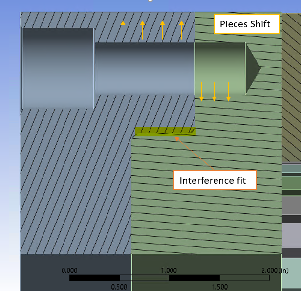
The bolt has been held perfectly still from the displacement constraint in timestep 1, and of course the two rings have skewed per their interference fit resolution. So in a sense, am I adding a pretension that is misaligned? I've attached some pictures that hopefully illustrate what I mean.
My other question regarding the modelling of the physical bolt is this: I've modelled the bolt using a shank diameter that represents the tensile stress area (A_t), so my bolt diameter is undersized from nominal. Would this cause issues with the contact elements assignments? I've increased the pinball radius and they seem to be working, however I'm you can see the presence of significant stresses in timestep 2 and 3 when I set the bonded contact areas to alive.
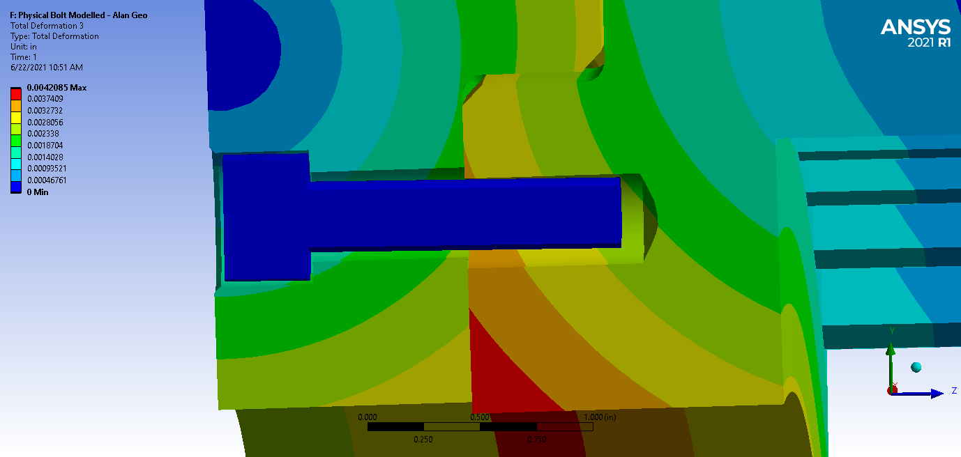 The above photo is timestep 1 - the interference fit is resolved and the bolt is completely stationary as intended. This displacement is exaggerated by a factor of 10 for plotting purposes
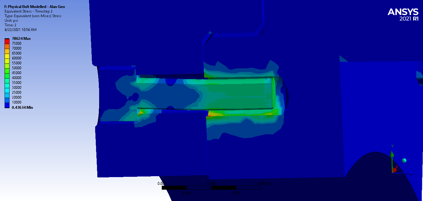 The above picture is the equivalent stress in timestep 2, the bolt is still restrained using a displacement constraint and the bonded contact areas are set to alive
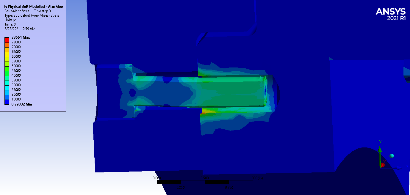 This above picture is timestep 3 where the bolt boundary condition is removed.
Viewing 2 reply threads- The topic ‘Combination of Interference Fit and Bolted Joint’ is closed to new replies.
Innovation Space Trending discussions
 Top Contributors
-
peteroznewman
 4858
4858 -
scabo
 1587
1587 -
Dennis Chen
 1386
1386 -
javat33489
 1242
1242 -
Shyam Prasad V Atri
1021
Top Rated Tags
© 2026 Copyright ANSYS, Inc. All rights reserved.
Ansys does not support the usage of unauthorized Ansys software. Please visit www.ansys.com to obtain an official distribution.
-
General Mechanical
Topics related to Mechanical Enterprise, Motion, Additive Print and more.
Combination of Interference Fit and Bolted Joint


Ansys Assistant

Welcome to Ansys Assistant!
An AI-based virtual assistant for active Ansys Academic Customers. Please login using your university issued email address.

Hey there, you are quite inquisitive! You have hit your hourly question limit. Please retry after '10' minutes. For questions, please reach out to ansyslearn@ansys.com.
RETRY