TAGGED: charge
-
-
August 9, 2024 at 6:03 am
handon
SubscriberHello,
I'm trying to get a dark current density of the device in the CHARGE simulation.


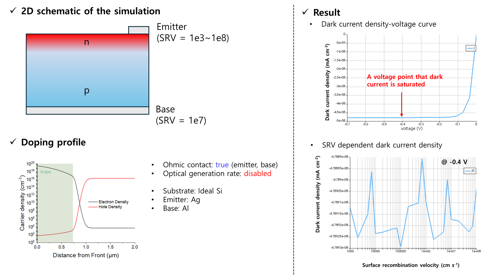
The concept of my simulation is like this:
1. Dark current is the current flowing through the device when there is no incident photon flux.
2. I can get the dark current density by applying a negative voltage to the device with no optical generation rate.
3. The dark current I0 equals Ish that leakage current caused by electrical loss (ex., surface recombination @ metal-Si contact).
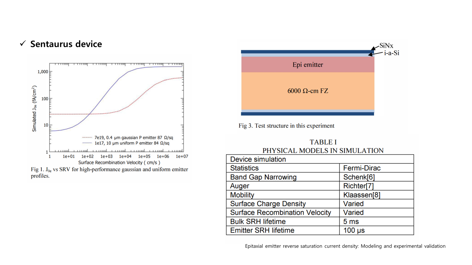
I also found other simulation works, and they showed that simulated J0 increased with surface recombination velocity (SRV) at emitter contact.
Although the simulation was performed by sentaurus device, not lumerical CHARGE, i thought it would be based on the same physics.I set a silicon device with an n-p junction to get a similar trend in J0 vs. SRV.
The dark J-V curve showed that dark current density is saturated from -0.4 V in the negative voltage range of -0.7 ~ 0 V.
I measured the simulated current leaving the base in the dark at a -0.4 V reverse bias by changing the SRV @ emitter from 1e3 to 1e8.
However, in the dark current density vs. SRV graph, there is no trend with an increase in SRV for J0, which suggests that surface recombination caused by metal-Si contact didn’t affect the electrical loss.Why didn’t the dark current increase with the surface recombination velocity of the emitter-Si interface?
-
August 12, 2024 at 6:59 pm
Amrita Pati
Ansys EmployeeHi Handon,
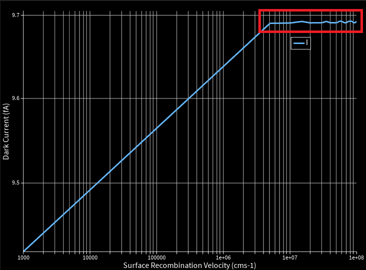
I ran a quick test on one of my existing pn junction files, and this is the I vs surface recombination plot, I obtianed:
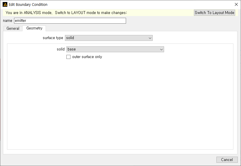
Although, I do see an increase in the current with increase in surface recombination (not as singificant as the figures you've shared), it seems to saturate after a certain values. Beyond which, I see some wiggles in the curve. I am wondering if for we are simulating that saturated portion. Have you changed all the parameters of your geometry and the material properties based on the paper? Quick question here: Are the hole and electron sat velocites set at same values in each simulation? Also, would you be able to share a screenshot of the "Geometry" tab of the emitter recombination BC? In the meantime, I will explore the topic a bit more and let you know if I have any findings.
Regards,
Amrita -
August 14, 2024 at 8:25 am
-
- You must be logged in to reply to this topic.


-
4858
-
1587
-
1386
-
1242
-
1021

© 2026 Copyright ANSYS, Inc. All rights reserved.


