

TAGGED: characteristic-impedance, dielectric-waveguide, hfss, waveport
-
-
May 6, 2021 at 6:36 pm
xuanding
SubscriberHi all,
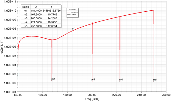
I try to simulate the characteristic impedance of a Si dielectric waveguide (Thickness x Width: 500um x 300 um) with wave ports.
- Ports were set to Zwave and "Do Not Renormalize"
- Port Zo(1,1) is supposed to be the characteristic impedance of the dielectric waveguide
May 7, 2021 at 12:25 amAndyJP
SubscriberSorry. Was thinking about more complex thing. Well, yes for a simple waveguide it should be Z11.
May 7, 2021 at 12:49 amSubscriberThe curve in the figure is not Z11. It is Port Zo(1, 1). When Wave port is matched, I think its port impedance should be the characteristic impedance of a uniformed waveguide.
May 7, 2021 at 12:53 amSubscriberThe result may be related to the wrong expectations about the fundamental mode.
Try defining a wave port with a mode (integration) vector. Or at least examine the field distribution carefully. These notches look like flips to higher order modes.
If results are still confusing, the dispersion and characteristic impedance problems are well analyzed by the eigenmode solver.
May 7, 2021 at 1:39 amSubscriberThank you for the advice.
I have tried wave ports with integration lines, and it gives me the same curve, but without spikes. The E field distribution looks normal. Some similar tests were done in ADS (Advanced Design System) by exporting a S2P file, and the impedance for fundamental mode in a Si waveguide is around 120-150 ohms at that frequency range, which I think is a reasonable number.
For the eigenmode solver, I'm a little curious how to check the characteristic impedance. The quality factor and resonator frequency are defined in the results, but I haven't find other parameters. Could you please direct me how to test Z0, or share with me some related materials? Thank you again.
May 7, 2021 at 3:56 amSubscriber>have tried wave ports with integration lines, and it gives me the same curve, but without spikes.
100%, the spikes are higher order modes crossing the fundamental mode. With the field vector you lock the mode and filter them out.
So, the results should be correct for your model and setup.
For better understanding, you should make an eigenmode section of your waveguide, and sweep the phase in order to see the dispersion, which will give you a hint on impedance. If it is bent somewhere, that will be the answer.
Don't forget that when no boundaries of the model are defined for "airbox" in HFSS, PEC condition is used. You should define some radiation and move the boundaries far away.
May 11, 2021 at 11:26 pmSubscriberHi Andy Thank you for the detailed instruction.
You are correct on the "spike" issue. I have updated my simulation setup.
I also tried eigenmode simulation. I'm able to obtain resonate frequency and dispersion, but have no clue to the characteristic impedance.
The characteristic impedance of microstrip line and metallic waveguide is able to extracted with drivenmodal collaborating with wave ports. And It was capable to simulate correct Z0 of dielectric waveguide using drivenmodal in HFSS 2019 R2 or older versions. However, I can't prove it now since our license doesn't support older versions due to "Electronic Pro, Premium, Enterprise product licensing". I think it is just data processing difference in 2020 R1, R2 and newer versions.
May 12, 2021 at 1:45 amSubscriber>but have no clue to the characteristic impedance.
you can not get it from dispersion only. you need a field solution. But you can see the peculiarities. Where the dispersion is straight, the impedance is a flat ratio of phase constants. Where it bends, the impedance will also go up and down.
We also upgraded from 2020R1 to 2021R1, and i see no differences, only improvements (like better lumped ports handling, other new features)... and recalling earlier versions, I see nothing broken, except legacy scripting commands disappeared.
May 12, 2021 at 1:47 amSubscriberP.S. you can take just the old license file to start the earlier version, and check, then put it back.
May 12, 2021 at 1:50 amSubscriberWe are using a license server and the old license has expired.
May 15, 2021 at 5:07 amSubscriberThe problem is figured out.
In HFSS 2020 or newer version, the simulation configuration for waveguide impedance is a little different from the older versions.
Drivenmodal
Proper wave ports, do not renormalize
Port type: Zwave
Frequency sweep type: Discrete
Then port impedance Zo(1,1) would be the waveguide impedance.
June 18, 2021 at 3:14 pmcbiurrun
SubscriberDear Andy I was trying to compute the characteristic impedance of a Coplanar Waveguide with the Fields calculator using the Fields computed in an Eigenmode Analysis but I am not much familiar with the calculator tool. I was trying to compute the Zpi impedance, but I keep receiving errors when I try to obtain the P and the I (also, I am not sure if I should take Jsurf, Jvol or Jm for this computation). Could you maybe give me some hints on how to achieve this? Thank you!
June 21, 2021 at 5:01 amSubscriberGetting an impedance of a complex structures with the field calculator only is a hard task. I use it for comparative study, but do not rely on absolute result values.
You have a waveport, which is a 2D model of the infinite line. So HFSS should offer you the impedance of your choice automatically. However.... well, it may be not what you expect, since it is not a true TEM mode there. But it may be the thing you need for matching. Then, you can either achieve a perfect matching with your DUT, and suppose the port impedance equal to the equivalent char. impedance, or pull it out of Z or S parameters by Colin.
June 21, 2021 at 8:35 amSubscriberHi again Andy, thanks for your quick reply.
When you have a, for example, Driven Modal analysis, yes, you have a Waveport and, in its definition, you are able to choose which impedance you want HFSS to calculate.
However, in the Eigenmode Analysis, you don't have any port. You have basically some info regarding dispersion (a relationship between Omega (i.e. complex frequency) and Betta (phase constant) and the Fields calculated for each mode.
What I was trying is to make a comparison between the impedance offered by HFSS when using a waveport and the impedance calculated from the Eigenmode solver for each mode, but I am not able (or better said, I do not have the knowledge of the tool) to calculate this impedance with the Fields Calculator.
June 22, 2021 at 12:43 amSubscriberAh, yes, that's why you use both, Eigenmode and DrivenModal. One for dispersion, another for the impedance. The wave impedance definition of Sexh*/Shxh* works well for TE(M) in a straight guide, and only along the poynting vector.
June 23, 2021 at 8:13 amSubscriberThe Fields Calculator would not let me do that. If I take E and H and try to make the Cross Product, I get an error. Also, how can I make the H*? Should I take the real and imaginary parts individually?
Thank you
Viewing 15 reply threads- The topic ‘Characteristic impedance of a dielectric waveguide extraction problem’ is closed to new replies.
Ansys Innovation Space Trending discussions
 Top Contributors
-
peteroznewman
 3757
3757 -
scabo
 1333
1333 -
Dennis Chen
 1168
1168 -
javat33489
 1090
1090 -
Shyam Prasad V Atri
1014
Top Rated Tags
© 2025 Copyright ANSYS, Inc. All rights reserved.
Ansys does not support the usage of unauthorized Ansys software. Please visit www.ansys.com to obtain an official distribution.
-


The Ansys Learning Forum is a public forum. You are prohibited from providing (i) information that is confidential to You, your employer, or any third party, (ii) Personal Data or individually identifiable health information, (iii) any information that is U.S. Government Classified, Controlled Unclassified Information, International Traffic in Arms Regulators (ITAR) or Export Administration Regulators (EAR) controlled or otherwise have been determined by the United States Government or by a foreign government to require protection against unauthorized disclosure for reasons of national security, or (iv) topics or information restricted by the People's Republic of China data protection and privacy laws.


