-
-
May 14, 2024 at 9:42 am
sriparna.2021rce15
SubscriberI have modeled a 3-D beam with dimensions: 100mm x 100 mm x 500mm in ANSYS workbench. ANSYS by default, is considering SOLID186 as an element type. The ANSYS modal results are based on Timoshenko beam theory, which does not match analytical results based on Euler theory. Can anyone suggest how I can force ANSYS to provide results based on Euler theory?
-
May 14, 2024 at 9:46 am
-
May 14, 2024 at 9:59 am
-
May 14, 2024 at 10:18 am
ErKo
Ansys EmployeeBeam4 is a beam (line element), so you can not use it on 3D solid bodies .
You need to define a line body.
See here how to define such a body (line) and how to analyse beams.
All the best
Erik
https://www.youtube.com/watch?v=5Ef5piegVh4
Erik
-
May 14, 2024 at 11:29 am
sriparna.2021rce15
Subscriberthank you for your response. Sir can you please tell me which real constants I need to insert in commands. After going through several posts, I have found to use the follwing commands:
et, matid, beam4
r,2,.....................
after r,2, I am unable to understand what parameters do i need to enter
beam cross section : 100mm x 100mm x 500mm
-
May 14, 2024 at 12:15 pm
ErKo
Ansys EmployeeHi
See this post for the real constants and help manual if needed:
/forum/forums/topic/euler-bernoulli-beam-theory/
use r,matid,AREA,IZZ,IYY,TKZ,TKY
and input the above (AREA=0.01*0.01 in your case I assume, etc).
I would suggest to learn the Mechanical (Getting started course),
https://innovationspace.ansys.com/product/get-started-with-ansys-mechanical/
and then also look into the APDL course as you need to learn what these commands mean when using them:
/courses/index.php/courses/intro-to-ansys-mechanical-apdl-scripting/lessons/overview-of-mapdl-lesson-1/
All the best
Erik
-
May 16, 2024 at 4:42 am
sriparna.2021rce15
Subscriberhttp://mae.uta.edu/~lawrence/ansys/el_beam/el_beam.htm
Thank you for your response. In the above article, it shows that it can be used for 3D element. So, is it possible or not.
-
May 16, 2024 at 8:27 am
ErKo
Ansys EmployeeHi
So beam4 is a 2 node beam element.
In mechanical one then needs a line body ( see here how to define such a line body
https://www.youtube.com/watch?v=5Ef5piegVh4 )
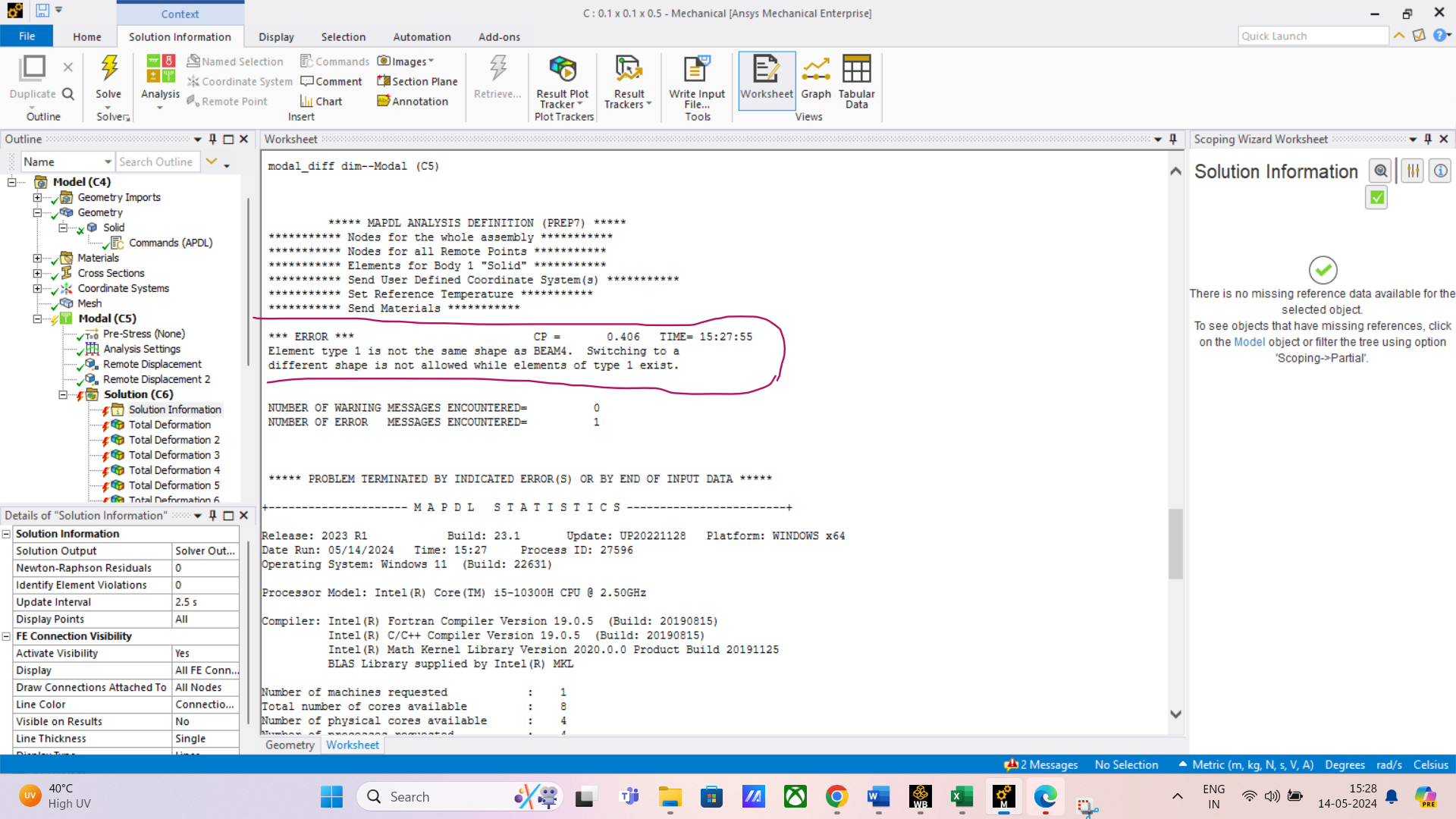
You have a 3D solid body which is meshed with HEX8 or HEX20 3D solid elements so hence the error.
To sum up the geometry created needs to be a line body not a 3D solid like you have, in order to use a beam4 element – look at the video again to see how to define/create a line body.
All the best
Erik
-
May 17, 2024 at 6:17 am
sriparna.2021rce15
Subscriberthank you for clarifying my doubt. I have serious doubts regarding Ixx, if you could help me with that, it would be of great help.
-
May 17, 2024 at 9:47 am
ErKo
Ansys EmployeeHi
Please see the doc./help:
Search for beam4 (...the torsional moment of inertia (IXX)).
See here hwo to open the help link (/forum/forums/topic/how-to-access-the-ansys-online-help/#:~:text=Open%20Ansys%20Workbench%20(or%20any,A%20browser%20window%20will%20open.)
All the best
Erik
-
May 17, 2024 at 12:20 pm
sriparna.2021rce15
Subscriberthank you for your help. I will work on it
-
June 5, 2024 at 10:16 am
sriparna.2021rce15
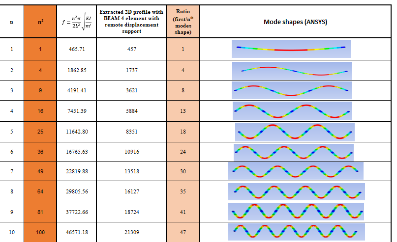
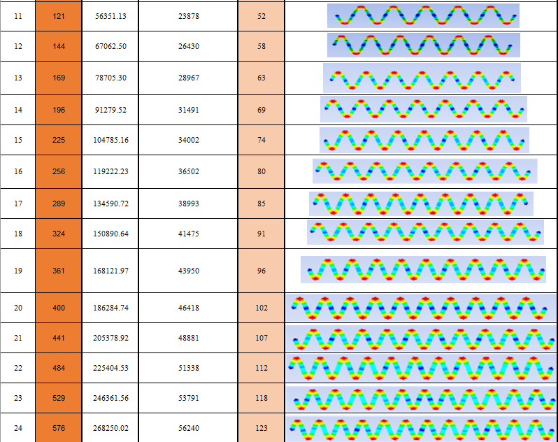
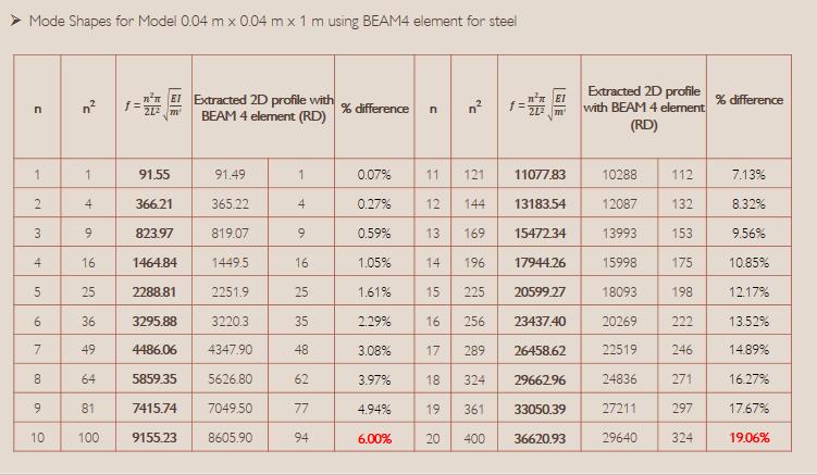
SubscriberMy problem was that I was not able to match the numerical frequencies corresponding to the bending mode shapes with the ansys result. I read about BEAM4 element, but the results are still not accurate. I have attached the properties of the model and the natural frequencies corresponding to the 20 mode shapes have been shown in the table along with the ANSYS result. It would be very helpful if you can help me to identify that whether there is some limitation in the ANSYS software for this geometry or something else. Dimensions of 3D beam: 150mm x 150mm x 700mm
-
June 5, 2024 at 10:19 am
sriparna.2021rce15
Subscriberjust to clarify I have tried this problem in 3D model and also as line body for BEAM4 element
-
July 4, 2024 at 9:39 am
-
July 16, 2024 at 2:31 pm
sriparna.2021rce15
Subscriberplease reply if someone knows about this topic. It would really help a lot
-
October 22, 2024 at 5:07 am
sriparna.2021rce15
SubscriberPlease help me with this problem
-
October 22, 2024 at 12:02 pm
peteroznewman
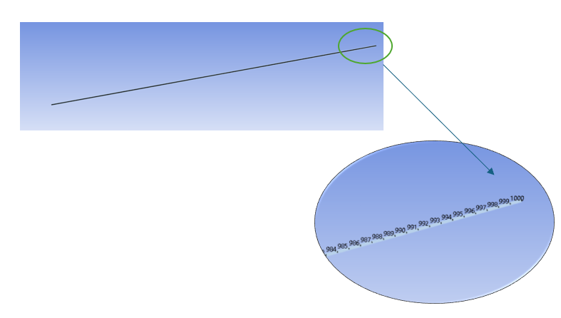
SubscriberTo get accurate results, you need at least 12 beam elements for each sinusoid along the beam.
For example, mode 2 has 1 sinusoid so 12 elements along the length is sufficient while mode 10 has 5 sinusoids so it needs at least 60 elements along the length. The higher modes need progressively more elements. It's okay to have more than the minimum number of elements.
How many elements do you have along the length for the tables you are showing above?
-
October 23, 2024 at 4:45 am
sriparna.2021rce15
SubscriberThank you for your reply sir.
I am unable to understand "elements". I mean are you talking about meshing?
Kindly tell me how to check about the number of elements, so that I can share the details with you.
-
October 23, 2024 at 6:35 am
-
October 24, 2024 at 11:43 am
peteroznewman
SubscriberOkay, 1000/12 = 83 so accuracy would start to degrade for modes with more than 83 sinusoids along the length. Mode 24 had 12 sinusoids.
Another source of error is whether the beam element is using a consistent mass matrix or a lumped mass matrix. Here is a YouTube video on that topic.
I know about this for the Nastran solver. I haven't looked up how the Ansys solver treats the mass in the BEAM4 element.
-
October 25, 2024 at 6:03 am
sriparna.2021rce15
SubscriberThanks for your reply and your valuable time.
I would just like to clarify......I extracted 55 mode shapes only and in 55 modes the error has crossed 50% from the theoritical. So, according to the 12 elements for a sinusoid....upto mode 166 there should be no error. Please comment whether my conclusion is right or wrong.
I would like to ask which mass matrix is accurate:consistent or lumped?
-
October 25, 2024 at 9:49 am
peteroznewman
SubscriberI was able to count the sinusoids in the deformation plots that only go up to mode 24. I don't know how many sinusoids there are at mode 55 but it's probably less than 83 so yes, the element count per sinusoid is probably fine. It was a potential source of error when I didn't know the element count.
The consistent mass matrix is more accurate. The lumped mass matrix is more efficient to compute solutions to dyanamic analyses.
-
November 5, 2024 at 5:10 am
sriparna.2021rce15
SubscriberSir, please guide me in checking whether lumped mass matrix is being used or not.
-
- The topic ‘changing timoshenko beam theory into euler theory’ is closed to new replies.


-
4949
-
1639
-
1386
-
1242
-
1021

© 2026 Copyright ANSYS, Inc. All rights reserved.

