-
-
October 20, 2023 at 6:29 pm
Rishav Baruah
SubscriberI want to see the change in stress and strain due to change in temperature in a solid model in ANSYS Workbench. For that i have inserted Thermal Condition and changed the temperature but the stress values in the distribution remained the same in the model even after temperature change. What should i do to see the change in stress due to temperature?
Also i have one more doubt although i could calculate the compressive stress in the solid model but i am not able to calculate compressive strain. How can i calculate the same?
-
October 20, 2023 at 8:03 pm
Armin
Ansys EmployeeHi Rishav,
Could you provide more information about the model, for example what boundary conditions were utilized? A screenshot will be helpful.
It is possible that stresses do not develop in the model since the geometry is free to expand or contract after the temperature change. -
October 21, 2023 at 5:06 am
-
October 21, 2023 at 9:47 am
Rishav Baruah
SubscriberI have done the above analysis in static structural analysis. Could this be the problem?
-
October 21, 2023 at 10:09 am
peteroznewman
SubscriberSeveral settings are required to see stress from a thermal condition.
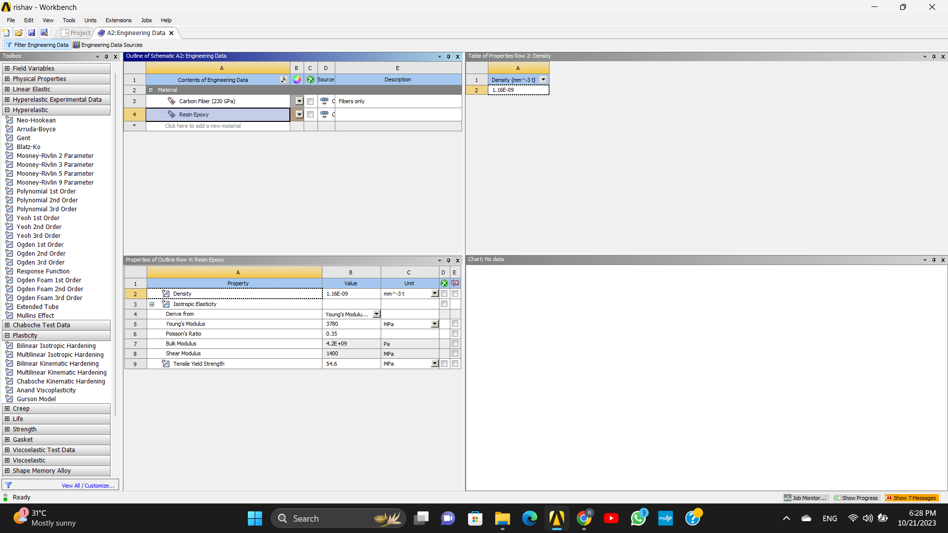
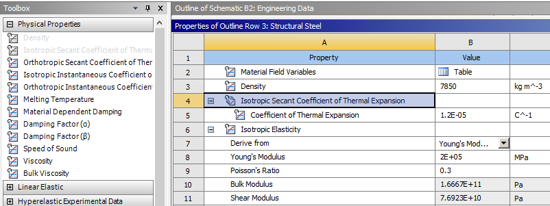
In Engineering Data, please show a screen shot of the material used and the Secant Coefficient of Thermal Expansion. What value is used? If that value is constant over the temperature range you are interested in, that is all you need. If the CTE changes over that range, then you can put several rows of CTE values and the temperature on each row.
Show a screen shot of all the material property values.
In Mechanical, check the material above is assigned to the bodies.
Click on the Static Structure analysis in the Outline, in the details window is the Enivronment Temperature, what is that set to (Ta)?
What is the Thermal Condition Temperature (Tb)?
How long is that part from end to end (L)?
Calculate by hand the strain you expect to see in the part from the displacement.
The displacement strain is 1 micron/L. What is that value?
Calculate by hand the strain you expect to see in the part from the temperature you applied.
The thermal strain is CTE*(Tb - Ta). What is that value?
Show the plot of Normal Strain in the Z axis.
-
October 21, 2023 at 1:15 pm
Rishav Baruah
SubscriberEnvironment temperature by default is 22 degree celsius and the temperatures to be given is 22,70,100,140,180 degree celsius. These temperatures are constant.The length of the body is 100 micrometer from one end to the other end. I want to assign the temperatures in the matrix portion which is the middle portion of the given geometry. The applied displacement is 1% of the length of the model.

-
October 22, 2023 at 10:38 am
peteroznewman
SubscriberYou must add an Isotropic Secant Coefficient of Thermal Expansion material property from the Physical Properties catagory of the Toolbox in Engineering Data. Do this for both the Resin Epoxy and the Carbon Fiber and enter the value of CTE for each one.
Apply the Thermal Condition to all bodies in the model. It would be wrong to assign the temperature to only the resin and not the carbon fiber.
-
October 22, 2023 at 10:42 am
Rishav Baruah
SubscriberThank you so much?
-
October 24, 2023 at 5:24 pm
Rishav Baruah
Subscriber -
October 24, 2023 at 5:39 pm
Rishav Baruah
SubscriberCan you please tell me the values for orthotropic secant coefficient of thermal expansion for carbon fibre(230GPa) along x,y & z directions and the values for isotropic coefficient of thermal expansion for resin epoxy?
-
- The topic ‘Change in stress and strain due to temperature’ is closed to new replies.


-
4929
-
1638
-
1386
-
1242
-
1021

© 2026 Copyright ANSYS, Inc. All rights reserved.

.png)


