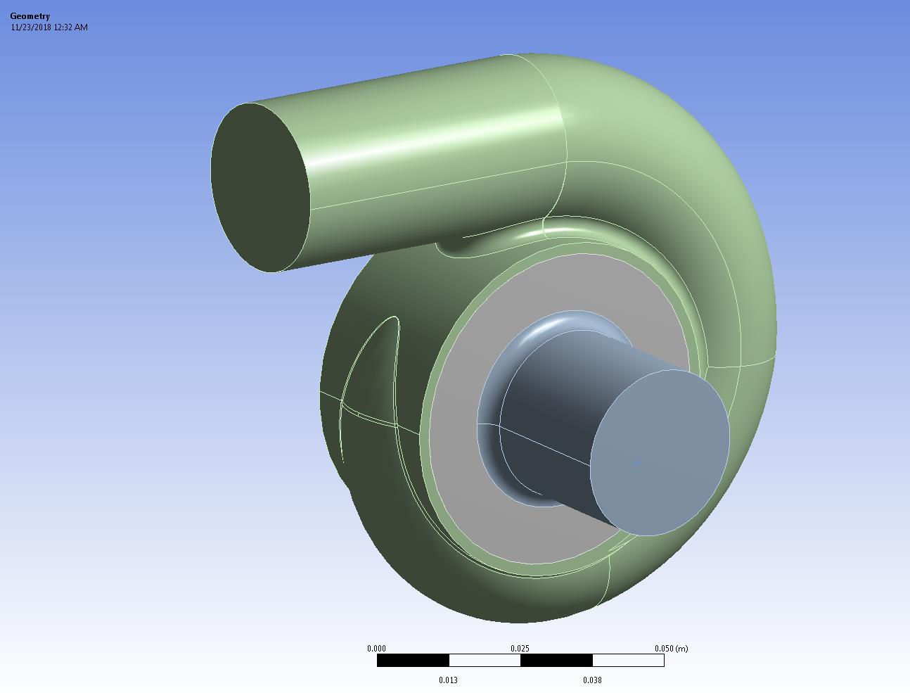
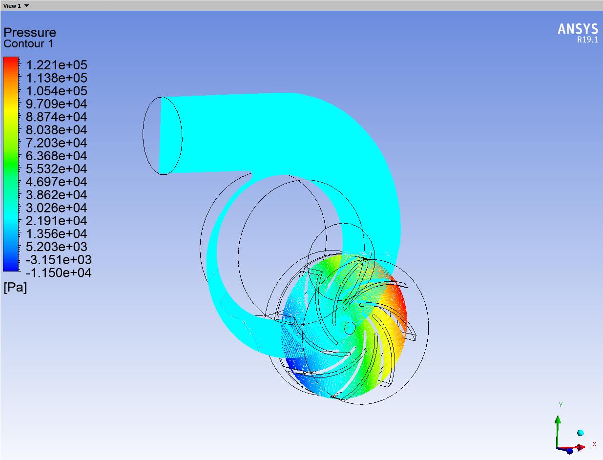
-
-
November 23, 2018 at 3:07 am
xgteml
SubscriberHello, I am going through Raef's exact pump simulation but I keep getting the message:
Warning: convergence tolerance of 1.000000e-06 not reached during Hybrid Initialization.
and
Error: floating point exception. Error Object: #f
When I attempt to run the calculation.
Any ideas what to try?
Link to video: https://www.youtube.com/watch?v=OJ_WjAlKQ3M&t=306s
Thanks
-
November 23, 2018 at 5:06 am
Keyur Kanade
Ansys EmployeeAre you using student version? What is cell count you created?
What is mesh quality? Please check quality in Fluent. The min orthogonal quality should be more than 0.1.
Please check your inlet conditions.
Please cross check other settings.
-
November 23, 2018 at 5:17 am
-
November 23, 2018 at 5:25 am
Keyur Kanade
Ansys Employeecan you please change Mesh Metric to orthogonal quality and post the image.
-
November 23, 2018 at 5:29 am
-
November 23, 2018 at 5:33 am
Keyur Kanade
Ansys EmployeePlease improve mesh so that your min. ortho quality is more than 0.1.
-
November 23, 2018 at 5:34 am
xgteml
SubscriberWhat is the best way to do this? Mesh element size?
-
November 23, 2018 at 5:46 am
Keyur Kanade
Ansys EmployeeCheck following videos.
First find where are bad elements. You may want to modify geometry at those locations. You may use different mesh sizing as well.
https://www.youtube.com/watch?v=AzvPxjNyr3w
https://www.youtube.com/watch?v=e_irQcWnTTs
https://www.youtube.com/watch?v=jSV7Pd7qAFU
-
November 23, 2018 at 6:04 am
-
November 23, 2018 at 6:16 am
Keyur Kanade
Ansys EmployeeFirst of all I think your geometry decomposition for inner rotating cell zone is not correct. Please check video correctly.
Please correct geometry decomposition first.
Then check the mesh quality video and follow steps to locate the bad element positions. Then take corrective action at these locations.
If you correct the geometry decomposition, I believe your mesh quality would be good.
-
November 23, 2018 at 6:35 am
-
November 23, 2018 at 6:37 am
Keyur Kanade
Ansys EmployeeThen check the mesh quality video and follow steps to locate the bad element positions.
Post image for the same.
-
November 23, 2018 at 4:45 pm
-
November 23, 2018 at 4:48 pm
-
November 23, 2018 at 4:59 pm
-
November 23, 2018 at 5:38 pm
-
November 23, 2018 at 8:52 pm
xgteml
SubscriberIs it most likely due to the mesh or something else?
-
November 23, 2018 at 10:15 pm
xgteml
SubscriberIt must be in the mesh. I am uncertain how to proceed.
-
November 24, 2018 at 5:46 pm
-
November 24, 2018 at 10:29 pm
-
November 26, 2018 at 6:52 am
Keyur Kanade
Ansys EmployeeIt must be mesh.
Can you please insert more images of the mesh. Some sectional views, some zoomed in views.
Also please reduce the time step. Make sure that in one time step mesh is not moved more than a cell length.
-
December 11, 2018 at 8:41 pm
xgteml
SubscriberThank you for the help. Just one last question, since this is internal flow, with a velocity inlet and pressure outlet specified, if the pump was scaled larger, would the results change or is it all relative?
-
December 12, 2018 at 4:09 am
Keyur Kanade
Ansys Employeeif geometry is scaled then other input parameters will also need to be changed.
if this helps you, please mark this as 'is solution' to help others on forum.
-
- The topic ‘CFD Centrifugal Pump Simulation’ is closed to new replies.


-
4939
-
1639
-
1386
-
1242
-
1021

© 2026 Copyright ANSYS, Inc. All rights reserved.


