We have an exciting announcement about badges coming in May 2025. Until then, we will temporarily stop issuing new badges for course completions and certifications. However, all completions will be recorded and fulfilled after May 2025.
3D Design

3D Design

Topics related to Ansys Discovery and Ansys SpaceClaim.

Centrfugal pump preprocessing

    • Lokesh K
      Subscriber

      I have a solid 3D solid cad model of centrifugal pump that includes both impeller and volute. How should preprocessing be done in ansys spaceclaim 2024R2 to take this cleanup model to the ansys fluent to do the MRF approach sinulations? Give me the step-by-step exact approach for both impeller and volute to create the fluid domain Can you please explain in details only for the fluid flow analysis with no CHT can anyone Give me a detailed explanation for how to do the preprocessing

    • peteroznewman
      Subscriber

      Read this Ansys Help page: https://ansyshelp.ansys.com/public/account/secured?returnurl=/Views/Secured/corp/v251/en/flu_th/flu_th_sec_mrf.html

      The basic steps in SpaceClaim are to hide the Impeller and on the Prepare tab, use the Volume Extract button to create the volume body inside the volute. Turn on the impeller and on the Design tab, use the Combine tool subtract the impeller from the volume body to get the total fluid volume. Note that by default the interference solid (identical to the impeller) is created so you must delete that to end up with just two bodies to transfer to Fluent.

      Construct surfaces to split the total fluid volume into two pieces near the half-way point between the outer faces of the impeller and the inside faces of the volute.  Now you have the rotating fluid body and the stationary fluid body.

    • Lokesh K
      Subscriber

      What should I do if both impeller and volute fluid domains are overlapped with each other?

    • peteroznewman
      Subscriber

      If the impeller can rotate, it does not overlap with the volute. Please reply with an image of a cross-section through the axis to show the impeller and volute.

    • Lokesh K
      Subscriber

      Thanks for the reply. Kindly review the section view

    • Lokesh K
      Subscriber
      In practical there is no overlap. However once after creating the enclosure region there is a overlap between impeller enclosure and volute fluid domain.
    • peteroznewman
      Subscriber

      Construct a solid body by revolving the orange lines below about the axis to divide the total fluid volume into two pieces near the half-way point between the outer faces of the impeller and the inside faces of the volute.  Now you have the rotating fluid body and the stationary fluid body.

    • Lokesh K
      Subscriber

      Thanks for the guidance. I have followed your instructions and created the reference solid body for the impeller and extracted the fluid volume without the impeller. Can you help me with the next step? I have attached the reference image

    • Lokesh K
      Subscriber

    • peteroznewman
      Subscriber

      It will be easier for me to help if you reply with a link to the .scdoc file in your Google Drive or other online file sharing site such as OneDrive or Jumpshare.  If using Google Drive, create the link so that anyone with the link can download the file.

    • Lokesh K
      Subscriber

      Hello Sir. Kindly use this link to access the model   https://drive.google.com/drive/folders/15IDQtfsxN8lz7r-m5JoRr8GDQiKUFTSv?usp=drive_link

    • peteroznewman
      Subscriber

      Hello Lokesh,

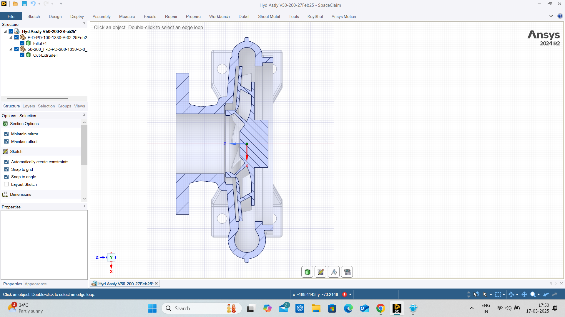
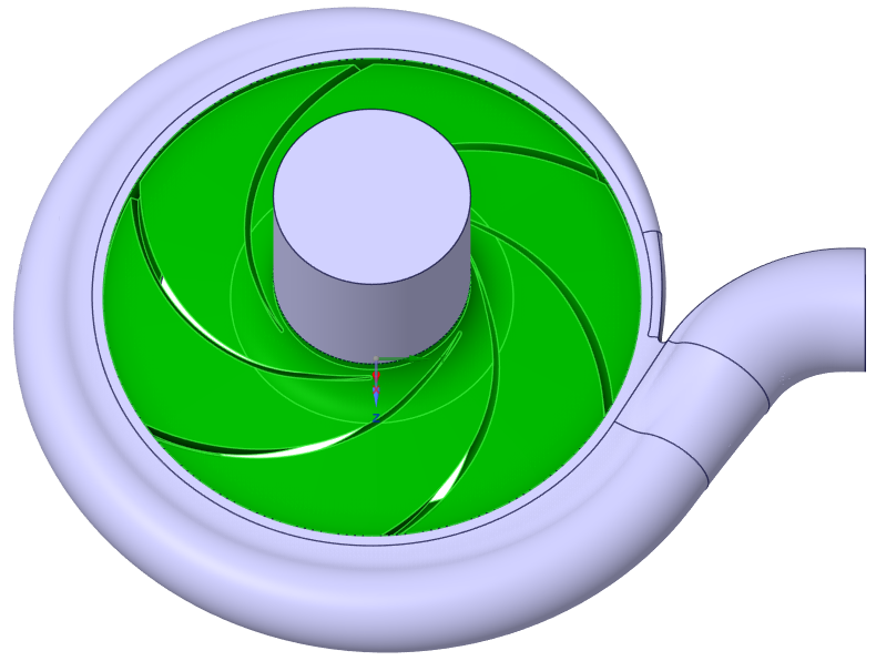
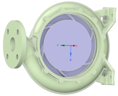
      I looked at your geometry and note there is a missing part. The impeller and volute show the inlet and outlet.

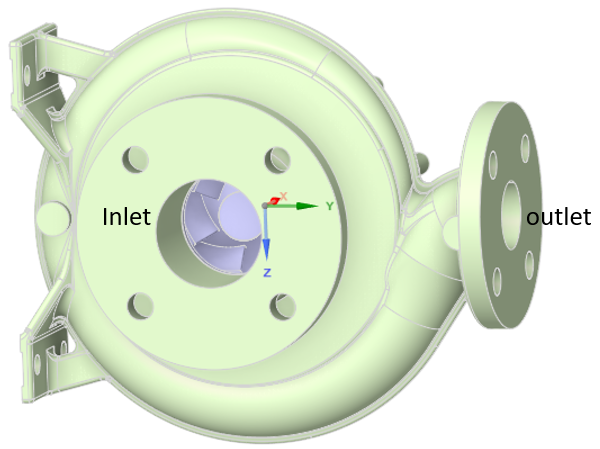
      But on the back side of this image, there is a missing cover that closes the back of the volute. Please add that part. I don’t know how close it comes to the impeller.

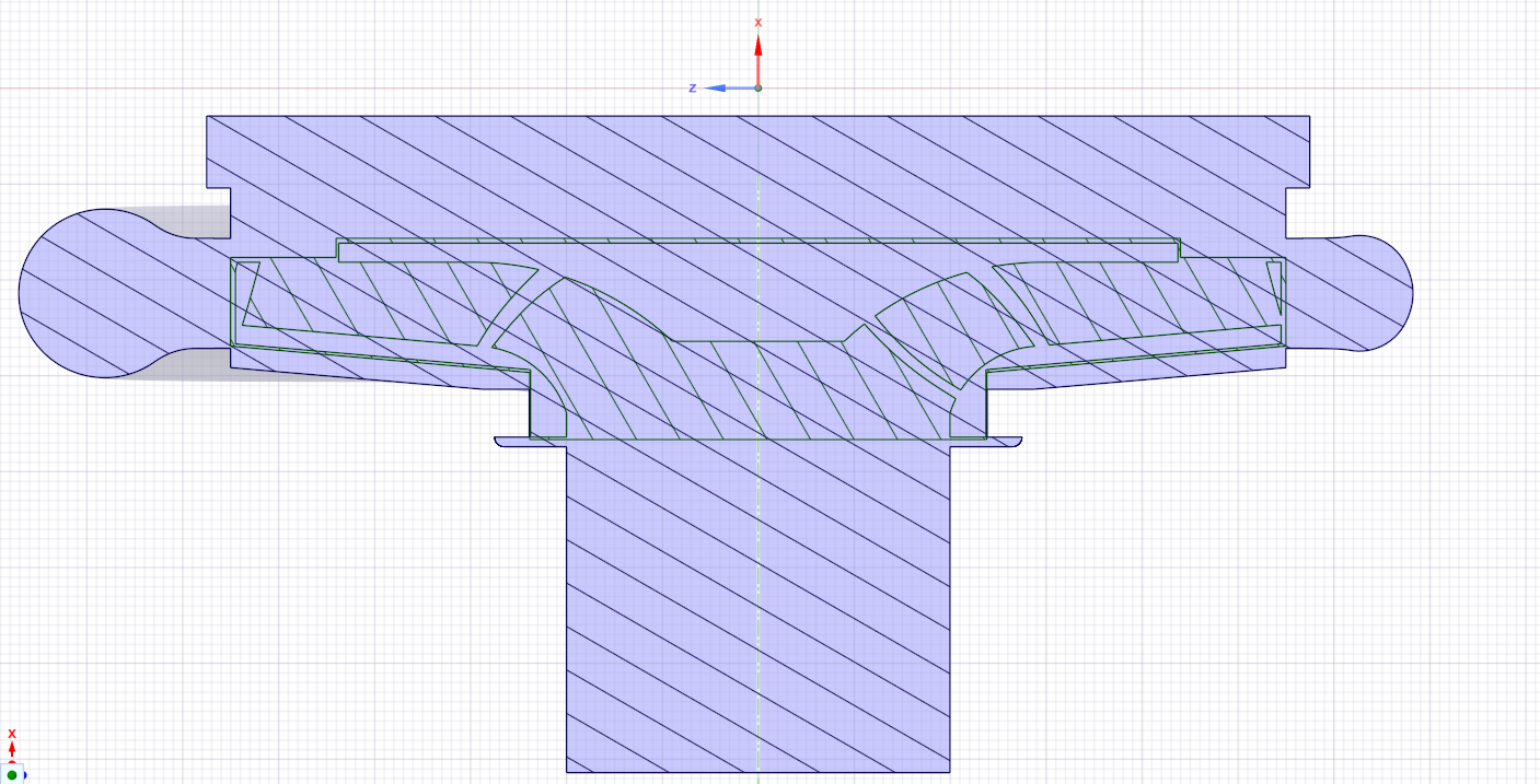
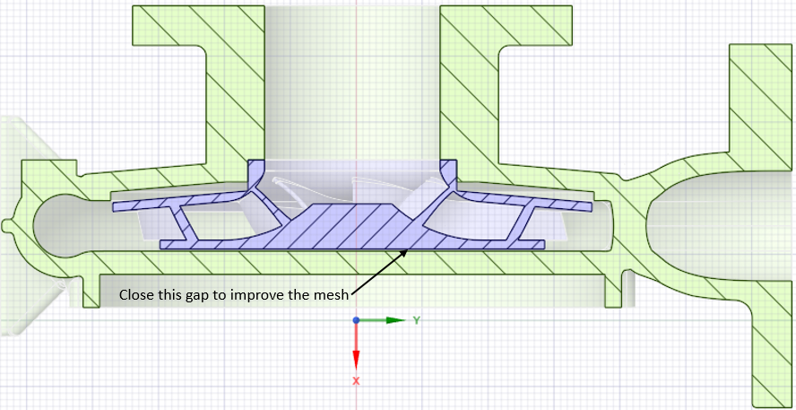
      In the cross-section below, you can see how the missing part is needed to define a stationary wall on the fluid volume.

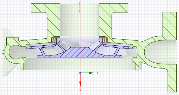
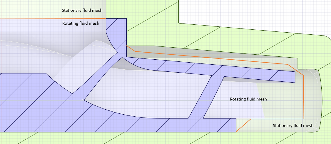
      In orange is the casing spacer ring. In reality you need clearance to allow rotation but no significant airflow passes through that gap and you will get a better mesh if you make the spacer ring ID the same diameter as the impeller hub.

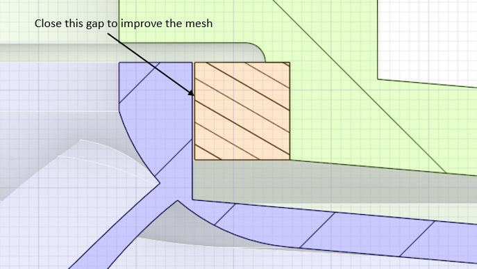
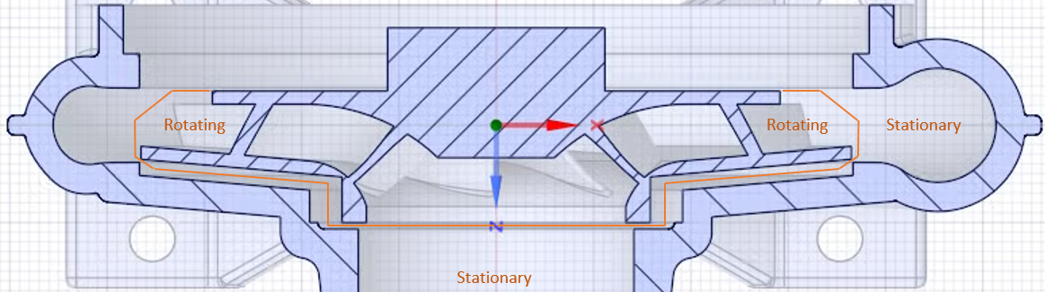
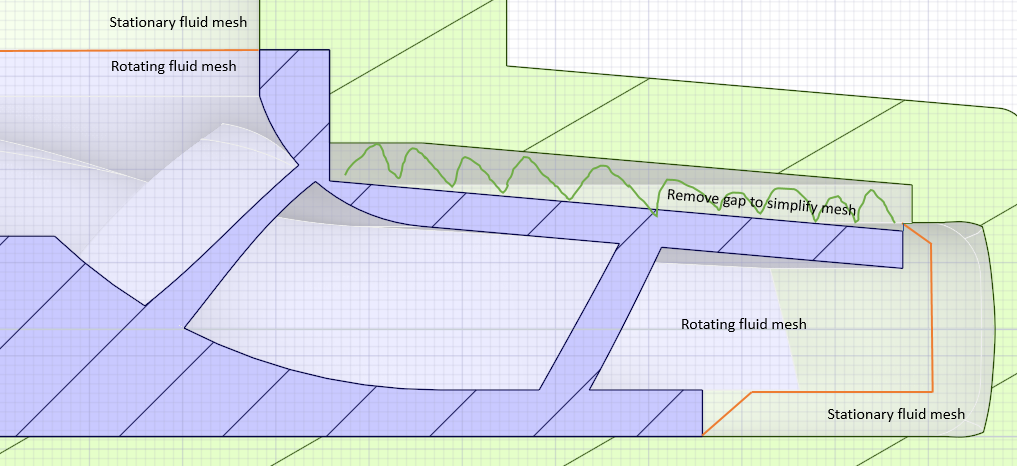
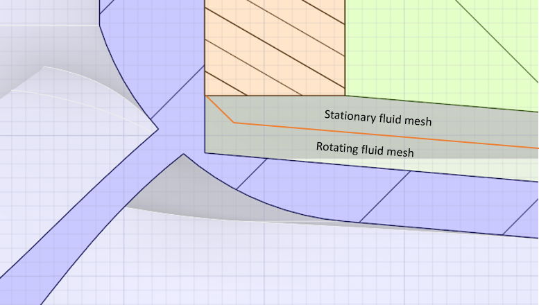
      Now you will create the rotating fluid body at the surfaces created by rotation of the orange lines.

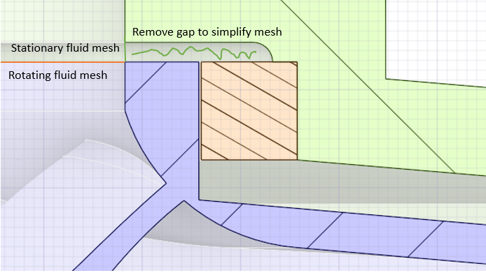
      Another simplification to the mesh is in the gap above the ring which could be deleted.

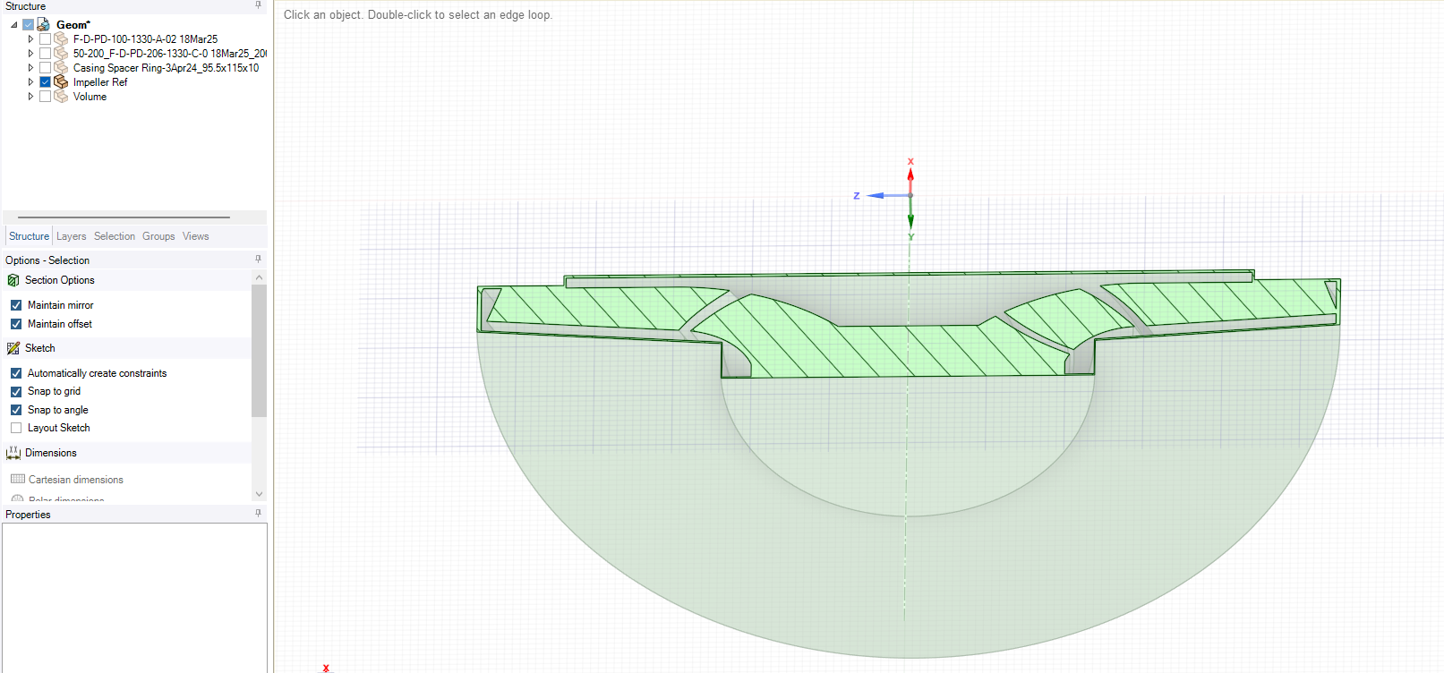
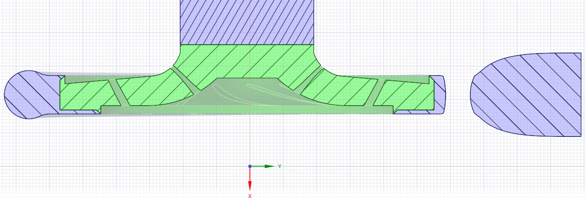
      Making those changes, it makes sense to merge the ring into the volute solid body. I also deleted the big hole in the volute where the cover would be bolted in and get this assembly.

      Here is the final result after pulling the impeller bottom face down 1 mm and fixing a 0.05 mm step in the volute cover.

    • Lokesh K
      Subscriber

      If I close the gaps, how can I create the fluid domain? 

    • Lokesh K
      Subscriber

      If possible, can you share the cleaned model with fluid extraction for both impeller and volute

    • peteroznewman
      Subscriber

      I recommend another simplification as shown below.

      Here is one cross-section.

      Here is the 3D view of the rotating fluid volume in green and the static fluid volume in purple.

      Here is an Ansys Mesh with default settings except for adding a Patch Conforming tetrahedrons method.

    • Lokesh K
      Subscriber

      Could you please share me the file with me ..?cleaned up model is more than sufficient 

    • Lokesh K
      Subscriber

      It seems this is pretty much new approach which you followed.Thos is not the approach I used to create the fluid domain.

    • peteroznewman
      Subscriber

      I am not an expert at CFD. A better mesh might be found by using Fluent with Fluent Meshing. I didn't yet include any inflation layers. However clean geometry is required for getting an acceptable mesh. Please tell me the approach you used to create the fluid domain.

    • Lokesh K
      Subscriber

      I have shared one file with you right in that way .I have selected all the external faces of volute and using volume extraction feature ihace created the stationary fluid domain 

    • Lokesh K
      Subscriber

      For impeller using the reference which created throughout the impeller and using Boolean operation I have subtracted the impeller by keeping volute fluid domain as the source 

    • peteroznewman
      Subscriber

      Please show the skewness element quality of the mesh on your fluid volume.

    • Lokesh K
      Subscriber

      Max skewness is 0.7.it is good to go for the analysis as pery knowledge.

    • Lokesh K
      Subscriber

      Is it possible share the file for my reference and learnings 

    • peteroznewman
      Subscriber

      Here is the SpaceClaim 2024R2 document with three solids that use Shared Topology to mesh the two static and one rotating fluid bodies. https://jumpshare.com/v/Iqri2Rqp6OxtZg9LrGOw

      If you post a question in the Fluids channel to get help with Mulitple Reference Frame method, please add a link to that New Discussion at the end of this discussion so I can follow along with this model.

    • Lokesh K
      Subscriber

      Sure will do that.Thanks for the file

Viewing 24 reply threads
  • You must be logged in to reply to this topic.