3D Design

3D Design

Topics related to Ansys Discovery and Ansys SpaceClaim.

Carburetor fuel model setting, ANSYS Forte

TAGGED: 

    • Hasan
      Subscriber

      I have seen ANSYS Forte tutorials on port fuel injection and direct fuel injection but not carburetor. What settings can I use for a carburetor fuel model such as in the tutorial chapter 7 ANSYS Forte? Chapter 7 ANSYS Forte tutorial is on a gasoline direct injection.

    • jcooper
      Ansys Employee


      HI Hasan:

      A carburetor is deceptively complex when it comes to modelling, because you would need a VOF multiphase approach that transitions to DPM  (what Forte is doing for sprays), in addition to FSI.  

      So, there are limitations in the state of the modelling. 


      1. Spray models are quite well-established and use lagrangian tracking, but a carburetor requires 2 phase modelling due to the accumulated liquid fuel in the carburetor bowl.
      2. The fuel level in the carburetor bowl is maintained by a float. This float would have to be modelled with FSI, as its position is a function of a force balance between liquid fuel from below and gravity acting down on it (similar to the float in a toilet bowl). This FSI capability is in Forte, but adds complexity to an already difficult problem
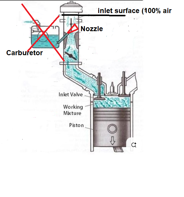
      3. The liquid fuel in the carburetor is drawn up into the air line via venturi (using the suction from the intake stroke) and enters the line as a tiny jet in crossflow.  This jet then atomizes into a fine mist and heads downstream to the engine with the intake air.  (Richer fuel mixtures behave a little less elegantly: When a carburetor runs fuel-rich, the mixture leaving can contain droplets of liquid, or liquid with bubbles, which cause the engine to run rough and also are very taxing for the VOF modelling, requiring a small timestep and a lot of mesh requirement (to resolve the fuel/air interface).


      (Here is a fun video that shows the situation quite clearly :)

      https://www.youtube.com/watch?v=toVfvRhWbj8 (You can start the video at 8:18 if you want to skip the backstory)


      So the issue is that the modelling requires VOF upstream of the orifice (carburetor bowl, float and fuel line) with VOF-to-DPM required downstream as the jet breaks up into DPM droplets. Fluent can transition VOF parcels to DPM droplets, but this capability is not yet in Forte.

      Even in Fluent, jets in crossflow alone are still quite a challenging problem without adding the complexity of moving mesh, FSI and free surface VOF

      I hope this helps.


    • Hasan
      Subscriber

      Thanks, yes it's complex but carburetors are still widely used and I hope I can find a way of simply assigning mass flow fraction of fuel droplets at a given size, with phase change. I am new to Forte, still learning how to use it and right now having problems with restart. Even though I have assigned a savings every one crank angle.

    • Hasan
      Subscriber


      Information found so far on net is that carburetor fuel droplets diameters are 10 to 100 micron, with DPM applied at inlet then I think this can be done.


    • jcooper
      Ansys Employee


      Oh sorry, I thought you were trying to model the entire carburetor. 

      There is no “setting” to simulate the presence of a carburetor, but since its job is to distribute tiny droplets evenly into the intake air stream, you can reverse-engineer something. To give the spray time to spread and break up, your model will have to include the orifice and venturi.  So you can start the intake geometry upstream of the venturi as shown below:

      The fuel passage would start from the nozzle that opens into the venturi. A solid cone injection nozzle is probably the most appropriate choice, as most hollow cones are generated by swirl with film formation. You could set a constant droplet size or Rosin Rammler distribution, depending on your literature findings.  The secondary droplet breakup models will break the entering droplets up further and create a fine mist.  The parameters of this model, and the incoming droplets, may have to be adjusted to generate smaller or larger particles downstream. (To find out what each breakup model parameter affects, mouse-hover over the parameter names):

      I hope this helps.


    • Hasan
      Subscriber

      Thanks will get to do this at some point, will find out what suitable academy fuel library file to select and start with default KH setting, then validate. Will have to find out what fuel chemistry file works best, not sure if Gasoline_1comp_49sp.cks works.

    • jcooper
      Ansys Employee

      If you have gasoline, if should work.  A small mechanism is best to start so that you have a case that turns around more quickly and allows you to learn from it faster.

    • Hasan
      Subscriber

      Thanks will give it a try as soon as I get this gasoline direct injection model going, ANSYS Forte is interesting though it has taken me a few months to get a grip. Maybe it's because I am a slow learner.

    • jcooper
      Ansys Employee

      There is a lot to know. I think Forte just has a long learning curve.

    • Hasan
      Subscriber

      Yes it's taking me time I don't why the "Save Solution & Restart" doesn't work always. I would have thought if one just press save then it will save and stop there, then switch off and once switch laptop on again then press the same button restarts from where last saved. Doesn't always work and I have been repeating the whole simulation over and over from scratch.

Viewing 9 reply threads
  • You must be logged in to reply to this topic.