-
-
July 28, 2021 at 2:26 am
KSD
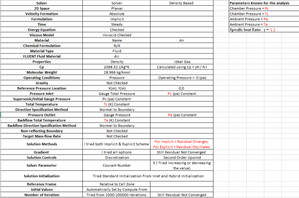
SubscriberI am trying to run truncated nozzle flow analysis exposed to ambient pressure, and I know the following parameters for the truncated nozzle problem.
Chamber Pressure (Pc) , Temp (Tc) and gamma.
Ambient Pressure(Pa), Temp(Ta).
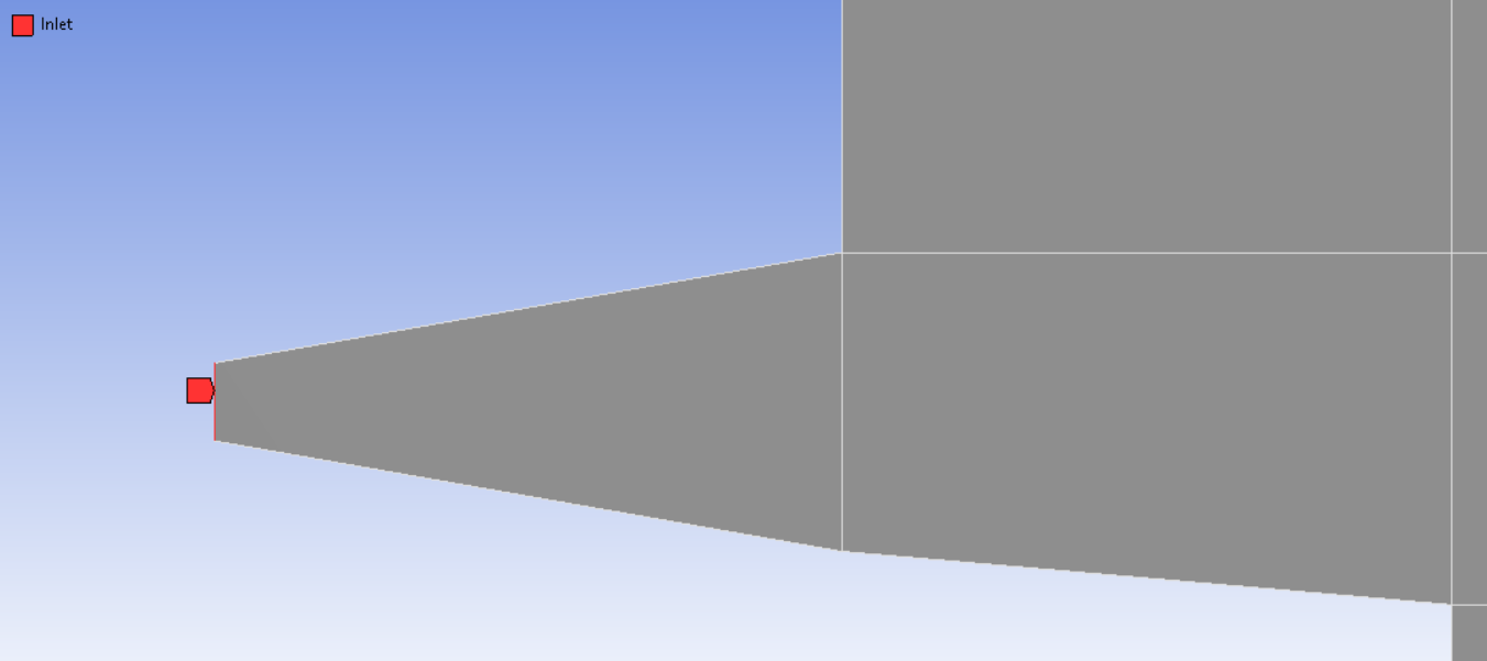
I created a structured 2d planar mesh with sufficient good quality (I think it is more than enough for Inviscid analysis), whose images are as shown
July 28, 2021 at 10:24 amRob
Forum ModeratorCould be the mesh (note, good cell quality does not always mean you have a good mesh), initial conditions, boundary settings, transient effects or the solver gods don't like you. The latter is rare, but more likely as you turn more models on without understanding what they do.
Please re-post the images as staff are not permitted to open or download attachments.
July 28, 2021 at 10:42 amKSD
SubscriberSir, thanks for responding , I am really struggling for the convergence for past few days, I don't know why because I have tried similar problem for normal conical or contour nozzles there it works fine.
Could you please check out the images, as I didn't know that staffs are not allowed to download files.


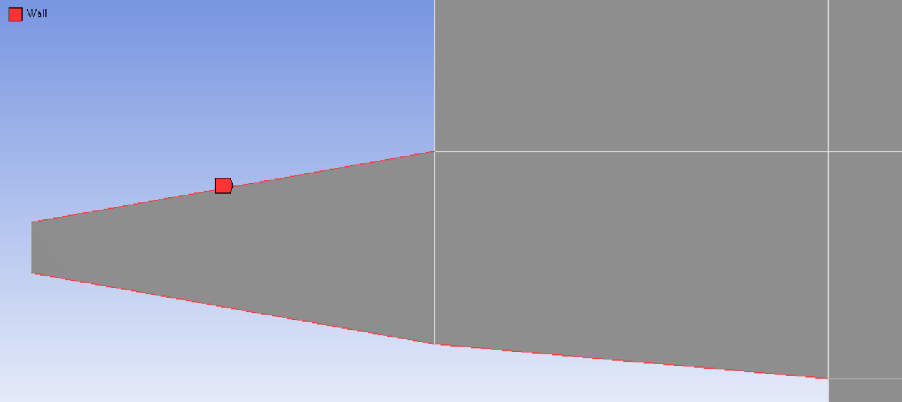
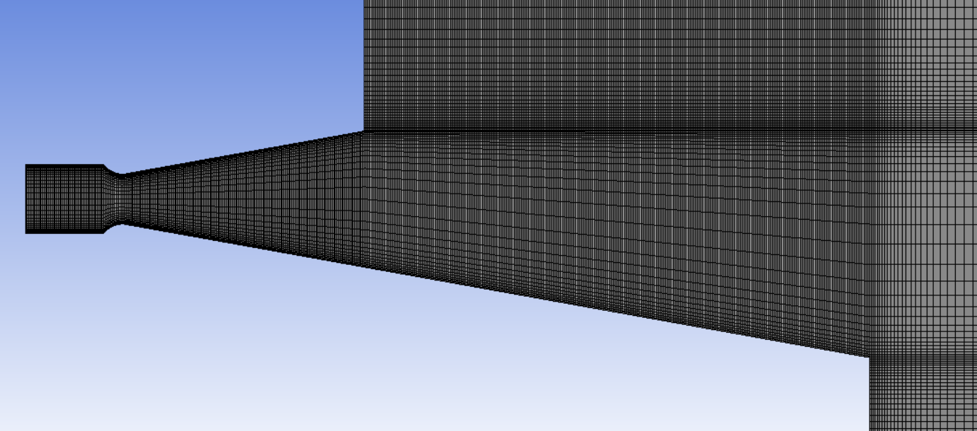
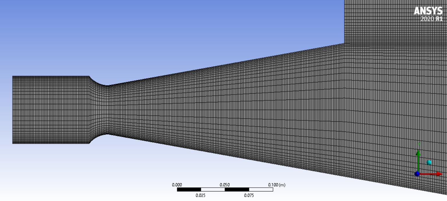
July 28, 2021 at 11:38 amJuly 28, 2021 at 11:44 amKSD
SubscriberI am new to this forum , I don't know whether my reply can be seen by others or not, so just for safety I am tagging you SirJuly 28, 2021 at 1:13 pmRob
Forum ModeratorWe do see the replies but have turned off most notifications because of the number of threads.
Part of the problem is the mesh: you need to avoid sudden jumps in cell size and stretched cells where the flow is changing across the cell. You're right to have a fine mesh near the walls, but you also need to ensure you resolve the jet and any other flow features. You've not stated what the supply pressure is, if it's sonic or subsonic, and if all boundaries are pressure (as opposed to mass or velocity). The latter makes the initial conditions important. The speed also guides the solver choice, Pressure based is good for Mach 2-3 so is most commonly used.
July 28, 2021 at 3:06 pmKSD
Subscribermy analysis is for supersonic case, my Pc = 6.895e+6Pa and Tc = 2777.778 K and Pa and Ta for ground ambient conditions.
Does that means for supersonic rocket nozzle analysis, the boundary conditions which I have used, are correct and I only need to focus on Mesh around jet due to presence of shocks or expansion waves ?
Can you please confirm this, If boundary conditions are correct then I think I don't have to worry about that part for the least. So that I can focus more on meshing around jet, as making structured mesh is becoming difficult due to slanted part of nozzle.

July 28, 2021 at 3:08 pmRob
Forum ModeratorI'd focus on a good hex mesh and be less worried about it being structured. That way you can resolve the flow.
As you're using all pressure boundaries you also want to read up on the Patch function to give the solver a better starting point: standard and hybrid initialisation may not be enough.
July 28, 2021 at 3:20 pmKSD
SubscriberOK Sir @Rob I got it, I am really happy that I got such quality help from an expert on that day itself when I posted the doubt.
Thanks a lot Sir.
July 28, 2021 at 4:10 pmRob
Forum ModeratorYou're welcome.
August 2, 2021 at 9:58 amKSD
SubscriberSir @Rob, I have tried various ways to refine the mesh along the jet but now my nozzle is canted (At some angle from horizontal axis) , main problem I face using biasing is that it gives biasing around wall but it also forces the same biasing in other domain where there is no wall effects at all, I then tried to use inflation method it is not working well around sharp corners and curvature.
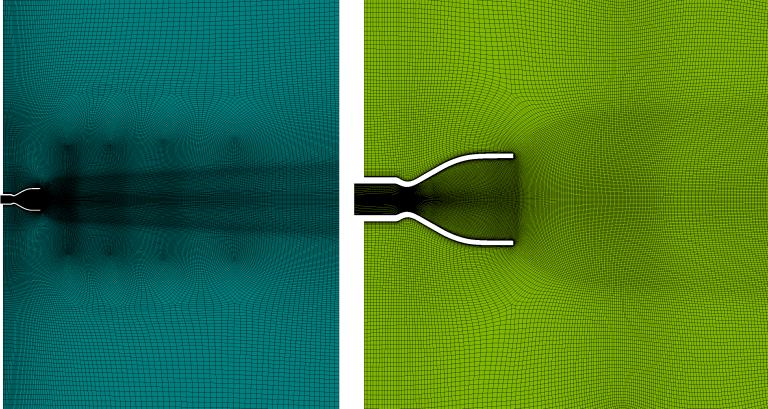
Is it possible to create such 2D Mesh with clustering of cells in jet region at certain interval as shown in the image below ? (For 2D case, Sphere of Influence is invalid after using Multizone-Quad/Tri Meshing)
 August 2, 2021 at 12:14 pm
Rob
Forum ModeratorI tend to use decomposition over spheres/bodies of influent. Just break the domain into smaller parts and you can assign finer mesh sizes to those bodies. Also remember that adaption is available in the solver if you need further refinement during the solution.
August 2, 2021 at 5:57 pmKSD
SubscriberSir, thanks for answering my queries,
I did decompositions in many ways, I am refraining myself from using mesh adaptation, as I have to do parametric analysis of the geometry, getting good solution using default mesh is necessary. (This is my understanding of mesh adaptation not sure I am right or not, according to me it is generally used to improve the cells with some conditions for e.g. gradient of a field variable or volume change smoothening, but the problem is I have to do mesh adaptation every time for different parametric cases)
I am getting okayish kind of solution (Mass Imbalance is less than 1% of entire domain) using explicit method, but with implicit solver the residuals blows off.
Sir could you please look into this post, as here I have attached the various decompositions types, I have tried.
/forum/discussion/30249/could-you-tell-me-why-the-inflation-layer-is-unevenly-distributed-in-curvature-part-of-2-d-domain#latest
August 19, 2021 at 6:08 amKSD
SubscriberSir, after completion of just 2D nozzle alone, I am again trying to solve this problem with domain as flow visualization is also important.
For 2D nozzle with 1mm unstructured cell sizing I am getting solution which are converging. (Even I did grid convergence test it was working well)
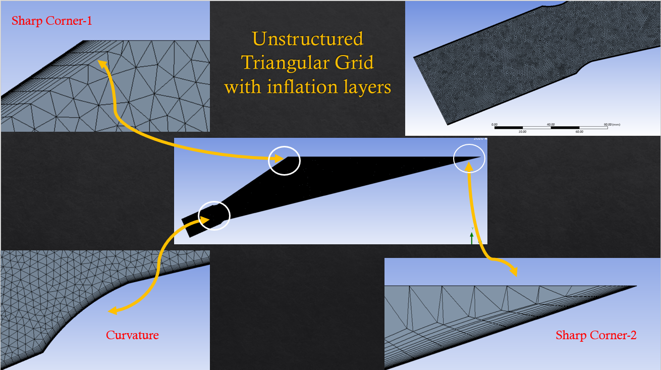
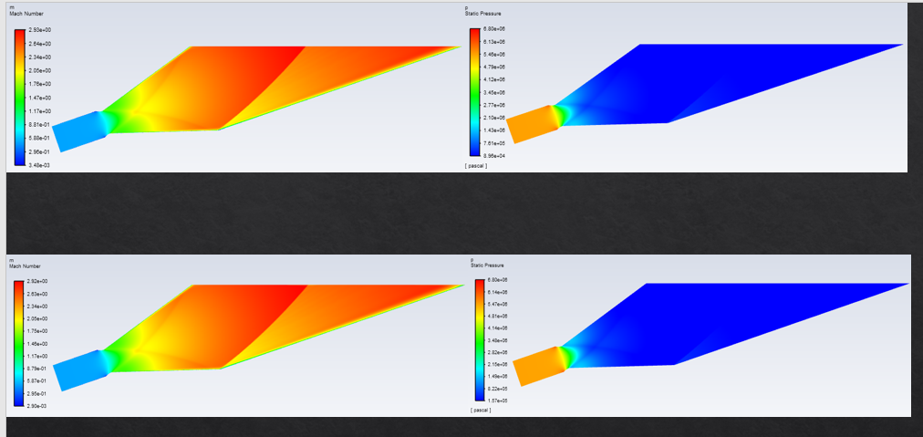 But the moment I add a domain to the nozzle my solution diverges for both type of mesh with and without inflation layers.
After many discussions you told me two important things
1) Check the variation of cells (And I have checked the area ratio its average value is close to 1 and max value is 48 due to inflation layers)
2) Use Adaptation (And according to me there is no point in using this if the solution doesn't stabilize first )
I have uploaded the steps as video in YouTube. And also you can see the mesh quality I am obtaining for the grid. (Please see the video, maybe I am doing something wrong in other settings)
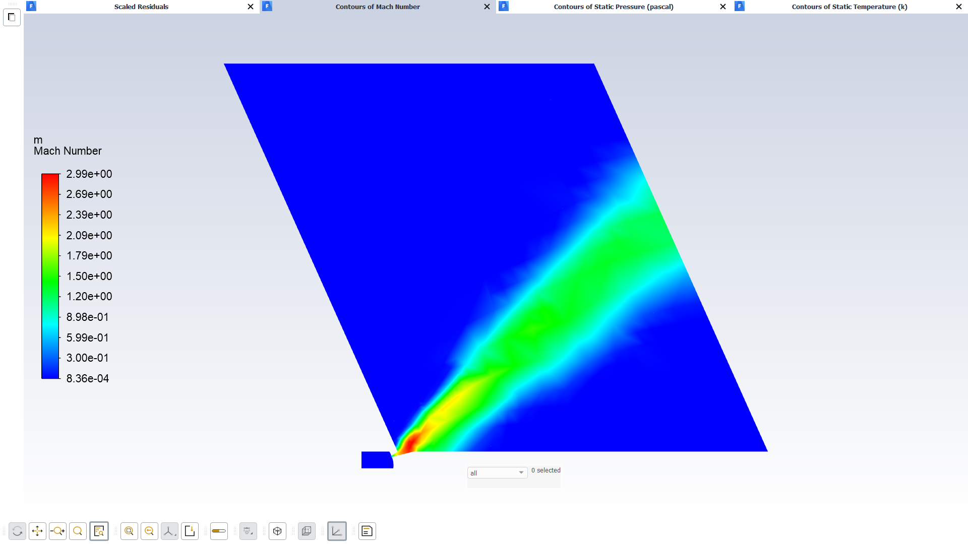
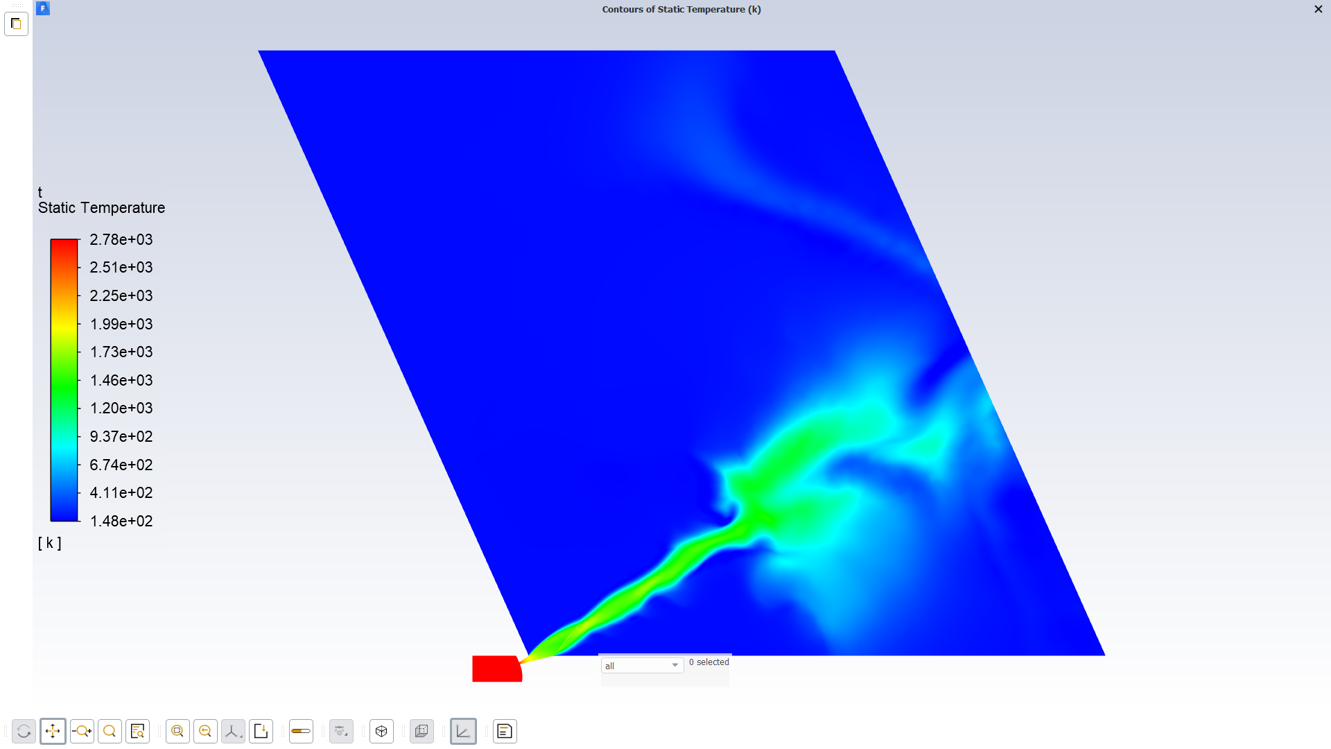
These are the results I obtained after 1000 iteration, you can clearly see that the solution is not stabilizing at any point it just blows off that's why adaptation cannot be applied.
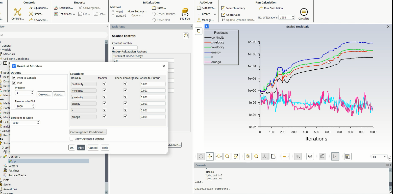 Even for unstructured mesh (both unstructured quad cells and unstructured triangular cells I have tried) the solution is not stabilizing, I don't know for nozzle alone it is working fine but as soon as I add domain to it for flow visualization solution blows off.
August 19, 2021 at 6:09 amKSD
Subscriber
August 19, 2021 at 10:38 amRob
Forum ModeratorThat could be mesh related - the skew cells as the inflation collapses won't help. Connect what you have above to a larger outer domain.
August 20, 2021 at 10:42 amKSD
SubscriberSir, as you mentioned I am trying to extend the domain, but sir can you tell me why even after giving 48 number of cores (which is in total present in the system), the task manager is showing around 16% usage of CPU, it is taking too much time to generate mesh (More than 5 hours but still it didn't create any mesh).
Can you tell me how can I increase the speed given that I have 48 Cores, 128 GB RAM and using Academic Research Licensed Ansys.
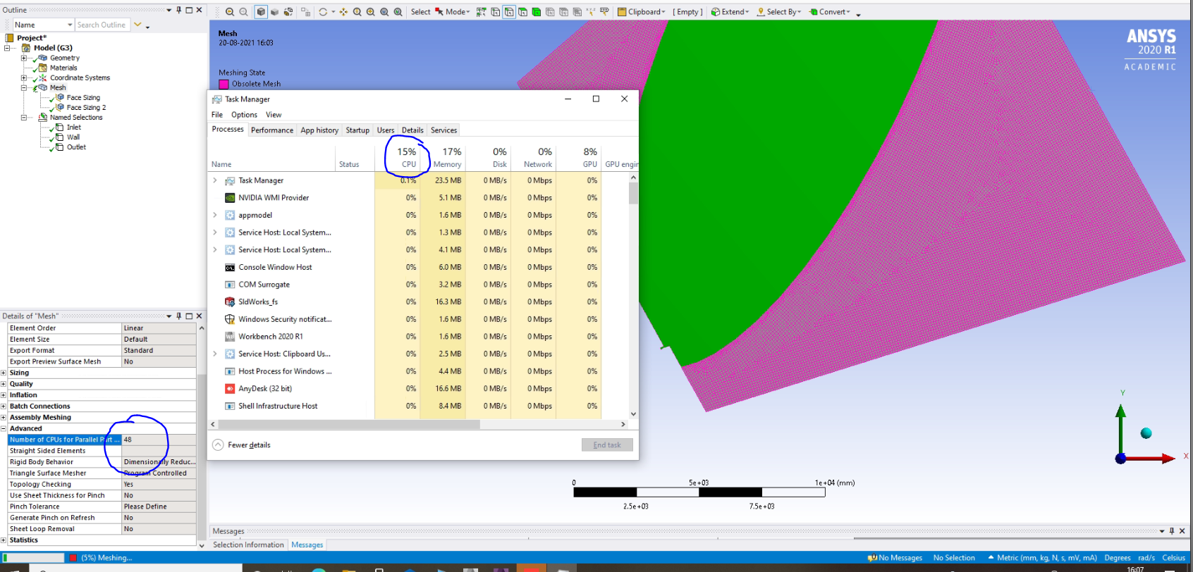
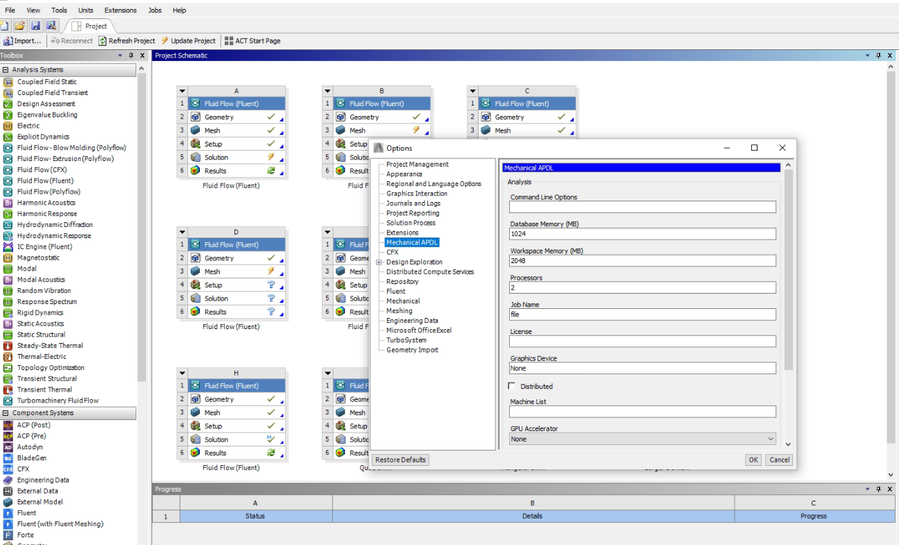 In workbench module when I go to tools>options>Mechanical APDL, I can see the that only 2 is written on Processors, Should I change this number to 48 and also should I change the Workspace or database memory?
I am afraid to change any default settings as I am not familiar with this.
August 20, 2021 at 12:42 pmRob
Forum ModeratorThe Ansys software will take what it needs from supplied resource, and in the case of meshing parallel doesn't scale as well as the Fluent solver. Given I've been helping an intern create a 15M cell model within 20-40mins on one core I'm not sure why you need so much compute for a 2d mesh. If it is taking too long check how many local sizings you've set and whether these conflict as that's what tends to slow things down. Check the nozzle is part of the same surface/volume as the extended domain as that may help avoid problems with inflation layers at the exit: also ensure the mesh is well resolved in the streamwise direction where you expect separation & flow gradients.
August 20, 2021 at 1:23 pmKSD
SubscriberSir, can you please check the video I uploaded as doubt, I think I have done nothing wrong.
August 20, 2021 at 1:35 pmAugust 20, 2021 at 3:36 pmRob
Forum ModeratorCheck the mesh around where the nozzle joins the main chamber and the mesh resolution along the jet. Jets don't break up like that so you may need to better resolve the gradients.
August 20, 2021 at 3:48 pmKSD
SubscriberSir, Actually sir the jet images which I got was just for justification of why I split the domain in desired manner.
Actually I have asked doubt related to the meshing speed then you said something related to surface issue
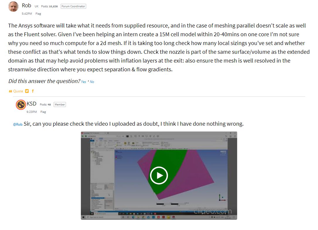 I will attach the video again, I forgot that you are solving many doubts in a day so you forgot about this. Sir actually my original doubt was why it is taking so much time to mesh a 2d domain even with 48 cores 128 GB ram system.
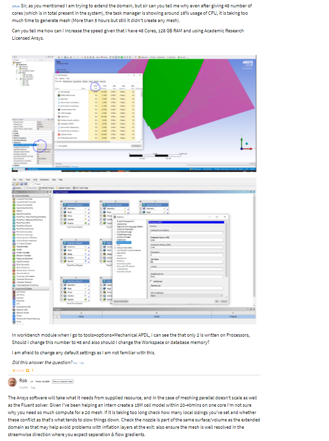
After this comment, I posted a new video showing the local sizing and how did I create the surface.
Sir, If it is confusing, I will create new post and ask it again.
Viewing 21 reply threads- The topic ‘Can you tell me the reason why my residual for truncated nozzle analysis is not converging?’ is closed to new replies.
Innovation SpaceTrending discussionsTop Contributors-
4969
-
1645
-
1386
-
1242
-
1021
Top Rated Tags© 2026 Copyright ANSYS, Inc. All rights reserved.
Ansys does not support the usage of unauthorized Ansys software. Please visit www.ansys.com to obtain an official distribution.
-
The Ansys Learning Forum is a public forum. You are prohibited from providing (i) information that is confidential to You, your employer, or any third party, (ii) Personal Data or individually identifiable health information, (iii) any information that is U.S. Government Classified, Controlled Unclassified Information, International Traffic in Arms Regulators (ITAR) or Export Administration Regulators (EAR) controlled or otherwise have been determined by the United States Government or by a foreign government to require protection against unauthorized disclosure for reasons of national security, or (iv) topics or information restricted by the People's Republic of China data protection and privacy laws.

