-
-
May 31, 2019 at 9:59 am
eagle_001
SubscriberHello, every one!
In the external flow problem, I used the Euler density based solver. The boundary condition is pressure far field. Now I want to make the flow
direction varies with time,I guess I can use the DEFINE_PROFILE macro. I know there is an example of defining the pressure profile as
following,
but what about the variable’s name for my case? According to the UDF Manual, I also checked the fixing the values of variables in the User’s Guide, but found a piece of description like this.
Is this mean I cannot change the x or y component of flow direction in the density solver?
Is anyone know the solution and could give me any help? Thank you very much!
-
May 31, 2019 at 6:07 pm
Amine Ben Hadj Ali
Ansys EmployeeYou can use FLUENT expressions instead of UDF. The latter wiuld work too. The passage you are referring is related to fixing components values using fixed values under cell zones. -
June 2, 2019 at 7:41 am
eagle_001
SubscriberHi, Amine! I really appreciate for your reply.
I have tried it as follow but I am still a little confused.
In the pressure far field definition dialogue box, I defined two input parameters, namely, x_direction and y_direction.
Then, these two parameters can be found in Parameters & Customization. As I cannot find a place to define their formula, I even try to use UDF to define them, but it doesn’t work.
I am afraid that I didn’t do it in the right way, so would you please describe your solution a little more detailed?
Thank you very much!
-
June 3, 2019 at 1:16 am
Karthik Remella
AdministratorHello,
Which version of Fluent are you using? You should be able to use expressions from Fluent 2019R1 and above.
Please refer to Section 5.1 in the Fluent Users Manual (2019R1) for additional details on Fluent expressions.
Thanks.
Best Regards,
Karthik
-
June 3, 2019 at 1:51 am
eagle_001
SubscriberHi, Kremella! Thank you very much for your reply!
It is a pity that my version is 19.2, so I can't try the Fluent expression method.
With the help of my friend, I succeed in doing this by UDF, and I'd like to share this with others. The UDF is as follow:
Â
DEFINE_PROFILE(x_component,tf_far,position)
{
face_t f_far;
real FRE = 5;
real flow_time = CURRENT_TIME;
real theta = 10*M_PI/180.0*sin(2*M_PI*FRE*flow_time);
begin_f_loop(f_far,tf_far)
{
F_PROFILE(f_far,tf_far,position) = cos(theta);
}
end_f_loop(f_far,tf_far)
}
DEFINE_PROFILE(y_component,tf_far,position)
{
face_t f_far;
real FRE = 5;
real flow_time = CURRENT_TIME;
real theta = 10*M_PI/180.0*sin(2*M_PI*FRE*flow_time);
begin_f_loop(f_far,tf_far)
{
F_PROFILE(f_far,tf_far,position) = sin(theta);
}
end_f_loop(f_far,tf_far)
}
Â
Best regards!
-
June 3, 2019 at 5:25 am
Amine Ben Hadj Ali
Ansys EmployeeNice.
-
- The topic ‘
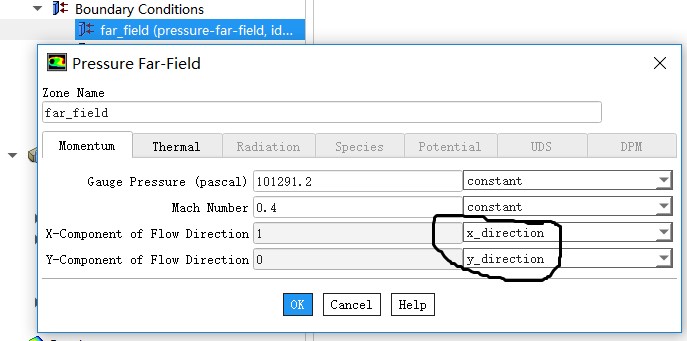
Can the x and y components of flow direction be changed by udf ?’ is closed to new replies.
-
4838
-
1587
-
1386
-
1242
-
1021
© 2026 Copyright ANSYS, Inc. All rights reserved.


