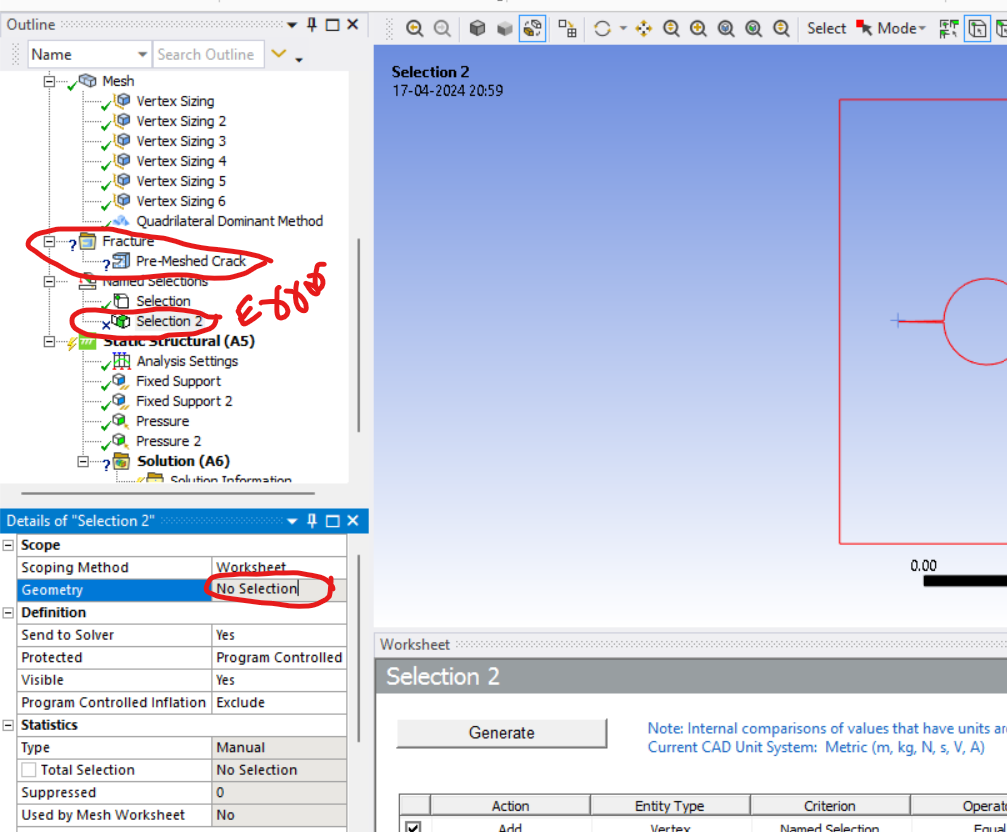
-
-
April 13, 2024 at 2:22 pm
lakshminarayana n
Subscriber -
April 15, 2024 at 1:42 pm
David Weed
Ansys EmployeeHello,
You need to insert a Fracture object so that the solver will recognize the highlighted vertex as a crack tip. To do this, right-click on Model and insert a Fracture object:
Â
Then right-click on fracture and choose Pre-meshed Crack:
For the crack tip node, you'll have to convert the geometric Named Selection into a Nodal Named selection (by right clicking on it and choosing Create a Nodal Named Selection). Set the Crack Tip field to this Named Selection and also be sure to set up a local crack coordinate system (it should be placed on the open side of the crack with the x-axis in the direction of crack growth and y-axis normal to the crack plane):
To ensure accuracy, test different levels of mesh refinement around the crack tip. You also want to achieve convergence among contours 3-6. Please see the Mechanical documentation here for additional details: Defining a Pre-Meshed Crack
-
April 17, 2024 at 3:38 pm
-
April 17, 2024 at 4:11 pm
-
- You must be logged in to reply to this topic.
- Preparing Solidworks Model for Thermal Desktop
- Steady-State Thermal in case of Layered Sections
- Advanced Turbogrid Topologies
- Why are the coordinates I specified and the coordinates outputted in the report
- NON MANIFOLD NODE WARNING
- Boundary Condition Definition
- PostProcessing in Aqwa: Getting Panel Pressure Time Response Series at Nodes
- Material properties get lost while importing .cdb file
- Workbench Meshing
- Difficulty in report files setup
-
336
-
125
-
93
-
53
-
50
© 2024 Copyright ANSYS, Inc. All rights reserved.