
TAGGED: beams-and-shells
-
-
December 19, 2021 at 9:36 pm
Rameez_ul_Haq
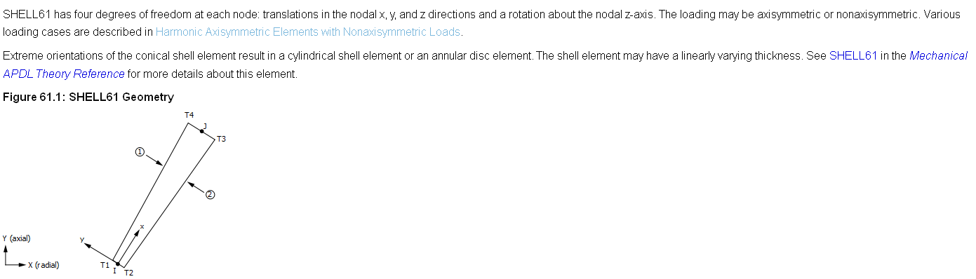
SubscriberI was going through the library of elements that is present in ANSYS. I saw SHELL61 element, which goes as follows.
December 20, 2021 at 2:00 ampeteroznewman
SubscriberA surface of revolution (about the Y axis) defined by a set of curves would be meshed with SHELL208 elements.
Both SHELL208 and SHELL61 elements are limited to axisymmetric models. Both elements must be defined in the global X-Y plane and the nodes must have positive X coordinate values.
SHELL61 assumes a linear elastic material and cannot be used with the large deflection option.
SHELL208 can do large strain, transverse shear deformation, hyperelasticity, plasticity and model composite layers.
The feature that the linear SHELL61 element has that SHELL208 does not is axisymmetric-harmonic applications such as a surface of revolution subjected to a horizontal earthquake. However, SHELL61 is a legacy element and if you have this application, Ansys recommends the general axisymmetric elements instead such as SOLID272.
December 21, 2021 at 8:23 pmSubscriberthank you for clarifying. Does the set of curves used for surface of revolution must lie on XY plane only?
please observe the picture below. A square surface body in a random plane (not XY or YZ or XZ).
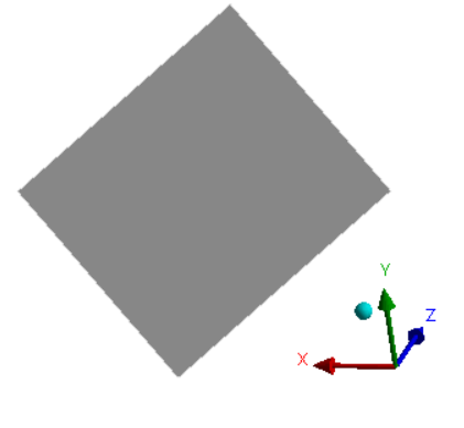 I want to reduce the DOFs on each of the node on this body from 6 (for shell) to 4. Like, 2 translations and 2 rotations, along a certain manually defined axis/co-ordinate system (not global). I am doing this to reduce the total DOFs within my model so that the time consumed for analysis contracts. Is this possible?
December 21, 2021 at 10:34 pmSubscriberMust the set of curves used for surface of revolution lie on XY plane only?
Yes, and they must be on the +X side of the Y axis.
If you have a planar object and all the loads and boundary conditions are planar, then you should transform that geometry to the XY plane to build a Plane Stress or Plane Strain model where each node has only 2 DOF.
If for some reason, you want to leave the planar object in 3D space, but the loads and boundary conditions are all planar, then you could reduce the 6 DOF at each node down to 3 DOF by creating a local Coordinate System on that Plane, where Z is normal to the plane. Apply a nodal Displacement constraint setting Z = 0 , leaving X and Y Free. Apply a nodal Rotation constraint setting Rot X and Rot Y = 0, leaving Rot Z Free.
The size of the matrix sent to the solver will be half the size if you do this.
December 22, 2021 at 9:05 amSubscriberthanks for the advice, sir.
The size of the matrix sent to the solver will be half the size if you do this.
I was thinking that since still the total DOFs at each node is 6, so the size of the matrix will be the same no matter even if I input the boundary condition at some DOFs on nodes equal to zero. Didn't know that applying boundary conditions, like by making UZ = ROTX = ROTY = 0 on all the nodes on the planar surface would actually decrease the size of stiffness matrix.
It kind alludes that the more nodes (and its DOFs) are included in the boundary conditions, the smaller the stiffness matrix and hence the smaller the time required for solution. What would you say, sir?
December 22, 2021 at 2:24 pmSubscriberThere is still overhead in dealing with six DOF, but it saves some time by setting three of them to a known value of 0.
The solver assembles the stiffness matrix, then partitions it to create a smaller matrix containing only unknown DOF.
The most time consuming step in the whole process is solving the matrix for the unknown DOF.
The answer from that solution is put back into the full stiffness matrix to do postprocessing.
Viewing 5 reply threads- The topic ‘Can I input a customized beam or shell element in my model?’ is closed to new replies.
Innovation Space Trending discussions
 Top Contributors
-
peteroznewman
 5824
5824 -
scabo
 1906
1906 -
Dennis Chen
 1420
1420 -
javat33489
 1305
1305 -
Shyam Prasad V Atri
1021
Top Rated Tags
© 2026 Copyright ANSYS, Inc. All rights reserved.
Ansys does not support the usage of unauthorized Ansys software. Please visit www.ansys.com to obtain an official distribution.
-


The Ansys Learning Forum is a public forum. You are prohibited from providing (i) information that is confidential to You, your employer, or any third party, (ii) Personal Data or individually identifiable health information, (iii) any information that is U.S. Government Classified, Controlled Unclassified Information, International Traffic in Arms Regulators (ITAR) or Export Administration Regulators (EAR) controlled or otherwise have been determined by the United States Government or by a foreign government to require protection against unauthorized disclosure for reasons of national security, or (iv) topics or information restricted by the People's Republic of China data protection and privacy laws.
