TAGGED: fluid-solid-heat-transfer, vof-model, welding
-
-
October 26, 2021 at 6:06 pm
tzwang
SubscriberThanks in advance for your interest.
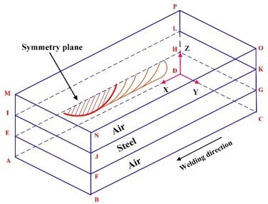
I'm designing for a molten pool model for TIG welding process via VOF. My application requires applying heat flux and momentum on the phase interface between air and workpiece. I found that there is heat, force, mass transfer function in VOF(on the interface tab), however, it seems that it only allows user-defined function for transfer coefficient instead of heat flux. Is there any way to define a heat source or a momentum source at the phase interface? I attached a sketch for my geometry.
If I hook up a define-profile UDF on the top surface of my workpiece (IJKL), will fluent considers this wall as a free surface? To be more specific, there will be a curvature when the workpiece (Designated as Steel) got heated up and melted. Will the IJKL wall catch the curvature and change its shape in this case? In another world, will the interface IJKL behave the same as phase interface or just remain as a solid wall during the calculation?
Many thanks!
October 27, 2021 at 10:43 amRob
Forum ModeratorThere isn't a face at the interface in topology terms so there isn't anything to apply a flux to. You need to look into source terms to mimic the heat input. Several others are working on this topic so search on the forum for their questions and discussions.
October 28, 2021 at 3:02 pmtzwang
Subscriber
October 28, 2021 at 3:04 pmtzwang
Subscriber Hi Rob
Many thanks for your answer!! It really helps.
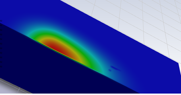
I thought about introducing a moving heat source via DEFINE_SOURCE, however, we also have to apply drag forces on the liquid surface for our application. I got my own UDF for the heat source and applied it to the IJKL faces in the diagram above. It successfully ran as a heat source, but it seems to be the heat was not able to conduct to the workpiece. Is there anything I'm missing in this case? Besides, there are also some black spots on the surface which doesn't match with the UDF profile.
Many thanks!
October 28, 2021 at 4:03 pmRob
Forum ModeratorTurn the node values off and see what it shows. Also check the two sides of that surface are connected.
Black spots in post processing can be missing facets in the iso surfaces and doesn't alter the result. Also check that you've not fixed the scale and clipped to range.
Viewing 4 reply threads- The topic ‘Calculation on Phase Interface using VOF’ is closed to new replies.
Innovation SpaceTrending discussionsTop Contributors-
4678
-
1565
-
1386
-
1242
-
1021
Top Rated Tags© 2025 Copyright ANSYS, Inc. All rights reserved.
Ansys does not support the usage of unauthorized Ansys software. Please visit www.ansys.com to obtain an official distribution.
-


