-
-
February 18, 2023 at 2:45 pm
javat33489
SubscriberHi all.
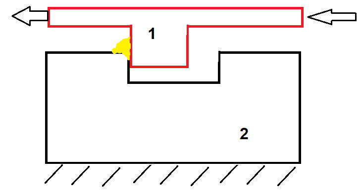
Please tell me how to calculate this.
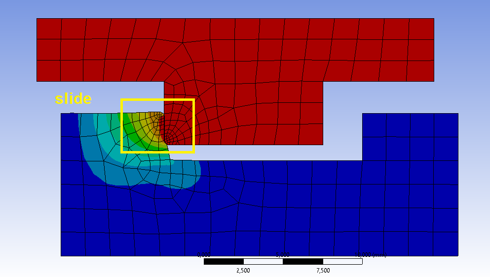
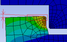
There are two parts made of steel. The second part is fixed, the first part has a protrusion and moves under force in the groove of the second part. At each touch, the end of the second part is deformed and a hill is formed (yellow on the screen), for example, when moving 20 times. How do I do this calculation to simulate this amount of movement, with the formation of a slide? My second goal is to measure the size of this slide. Which module in the workbench should I use? Please tell me the best way to do this calculation. Is it enough to have isotropic steel properties and bilinear isotropic hardening?
-
February 20, 2023 at 7:40 am
ErKo
Ansys EmployeeHi
I would suggest to go through some of our courses that are relevant:
Say getting started with mechanical, contacts, etc. See our courses here:
/courses/index.php/structures/
/courses/index.php/courses/getting-started-with-ansys-mechanical/
All the best
Erik
-
February 20, 2023 at 5:52 pm
javat33489
SubscriberTell me in which module it is better to solve this and how to make the slide form from a given number of stresses of the model elements.
-
February 21, 2023 at 5:42 pm
javat33489
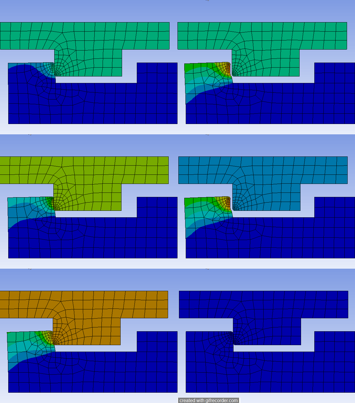
SubscriberPerhaps you misunderstood me. I'm talking about the fact that if you simulate a static analysis, one part deforms another, and makes a slide. But when the part moves away from the second part, the slide will become straight again.
And I need the slide to remain, in addition, with each repeated touch, the slide will be more, for example, 20 touches. And after 20 touches, I want to measure the size of the slide.
-
-
February 22, 2023 at 3:07 pm
Claudio Pedrazzi
SubscriberThis is clearly a highly nonlinear problem. So you need to get an introduction to using nonlinearities. It is nonlinear for at least three reasons:
- material (get plastified)
- large displacements
- contacts
About what WB-analysis type to use: it could be static, if the process is slow enough (meaning, the amount of kinetic energy is small compared to elastic energy). I would anyway begin with a static analyis of one “shot”. When it works as espected, you could increase complexity and make it dynamic, with the correct speed: then compare the results between static and dynamic. This will give you an hit if it is worth while the added complexity to do a dynamic (transient) analysis.
Concerning the material to use: my answer is always the same, a little my philosophy about simulation. Use the most simple (nonlinear) material model that can reproduce the general behavior that you expect (so a bilinear hardening would be ok). When the model begins to work and give reasonable results compared with the reality, than you can increase complexity. It is my opinion that for such a highly deformed behavior you need to use the best approximation you find for the material stress strain curve (many points).
hope this helps.
-
February 22, 2023 at 5:01 pm
javat33489
Subscriberi will use bilinear isotropic hardening means I will solve this problem in a transient? Can I set the accumulation of slides for the material there for multiple touches of two parts?
-
February 23, 2023 at 5:31 am
Claudio Pedrazzi
SubscriberI do not necessarily agree that you should use a transient, as I wrote above, I would at first try with a static analysis, and when it works, step the complexity up and go to a transient. But since you insist: give us an idea of the speed of this phenomenon: is this a "shock"? how long does one "touch" take? 1 second, 1 tenth of a second? how is the speed of the moving part?
A transient IMHO is appropriate when there are comparatively large kinetic energies involved.
And I do not understand the question "can I set the accumulation of slides for the material there for multiple touches of two parts?"
What do you mean with "set"? If the simulation works as expected, the increasing amount of deformation will be a result of the simulation itself, you will not have to "set" anything.
-
February 23, 2023 at 9:45 am
javat33489
Subscriber
-
-
February 23, 2023 at 9:54 am
Claudio Pedrazzi
SubscriberHappy that it is working as expected!
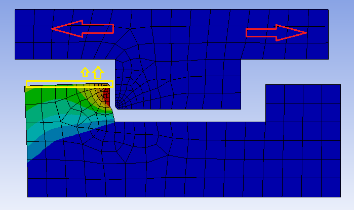
To my knowledge you cannot "measure" anything in the deformed shape, but what you certainly can do is to plot for example the vertical component of the deformation and use the sample probe feature selecting appropriate nodes and take the difference between the maximum vertical and an "undeformed" node. Or with more sofisticated approaches, you could define a path along the horizontal surface of interest, and plot (again) the vertical component of the displacement. And finally, at a third level of complexity, you can program some APDL-snippet extracting the same information, operating on it and finally cleanly writing it out on a file, each time a new line. Just my two cents.
-
- The topic ‘Calculation of work hardening of the end face of the part’ is closed to new replies.


-
4678
-
1565
-
1386
-
1242
-
1021

© 2025 Copyright ANSYS, Inc. All rights reserved.

