-
-
August 1, 2022 at 4:22 pm
francisco.freire.fernandez
SubscriberHi,
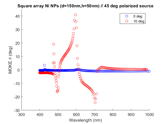
I am trying to simulate the MOKE rotation and ellipticity of a periodic array of Ni NPs. I followed this article to set up my simulations and took the Kerr rotation from the polarization ellipse analysis group. I use a BFAST plane wave incident at 0 or 10 deg, 45 deg polarization angle, periodic boundary conditions along x and y, and PML along z. Compared to the 0 deg incident plane wave case, I obtained Kerr rotation values 40 times higher at certain frequencies. I wonder, could this be an artifact due to my choice of boundary conditions, position of the analysis group, or something else?

Thanks!
-
August 2, 2022 at 10:57 pm
Guilin Sun
Ansys EmployeeWhen BFAST is used, it automatically override the original "priodic boudary conditions" with its own special boundaries to keep the incident wavefront to be planar. From your result it is not oviously wrong. But make sure you chose the correct order. Please check if there is any higher-order diffraction. If large diffraction angles are there, the PML performance may be degraded. If so, you may need to use "Steep Angle PML", and use more number of PML layers if mesh size is small. you can set roughly the PML half wavelength thick.
In addition, please check the resonance. If there is strong resonance, the simulation my need longer simulaiton time and smaller autoshutoff min.
-
- The topic ‘Calculation of magneto-optical Kerr rotation’ is closed to new replies.


-
4683
-
1565
-
1386
-
1242
-
1021

© 2025 Copyright ANSYS, Inc. All rights reserved.


