TAGGED: photonics
-
-
April 5, 2023 at 9:52 am
RUI MA
SubscriberHi,
I am using FDTD to calculate the transmission of the TE0 mode in a 180 degree adiabatic bend in order to reduce the bending loss. The width of the bend is swept. I use mode expansion monitor to check the transmission of the TE0 mode.
However, the results of the sweep are not reasonable, because the transmission of the TE0 mode is much lower than the results shown in this paper:D. Liu, L. Zhang, Y. Tan and D. Dai, "High-Order Adiabatic Elliptical-Microring Filter with an Ultra-Large Free-Spectral-Range," in Journal of Lightwave Technology, vol. 39, no. 18, pp. 5910-5916, Sept.15, 2021, doi: 10.1109/JLT.2021.3091724. I am not sure if the settings of the mode expansion monitor is correct. I assume therewill be wispering gallery mode at the apex of the bend, but the mode expansion monitor will only collect the transmission of the TE0 mode.Â
-
April 5, 2023 at 4:35 pm
Guilin Sun
Ansys EmployeeComparing result with others can be challenge, as you may not know the details of their device, such as material property, simulation settings. Please refer toÂ
Ansys Insight: Why my simulation result is different from published paper or experiment?
Actually you can use port instead of mode expansion monitor.
you can also move the source/port/monitor a little away from the junctions between the straight waveguides and the bend.
Â
Â
-
- The topic ‘
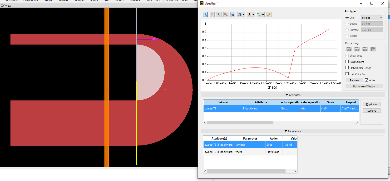
Calculating the transmission of the TE0 mode in a 180 degree adiabatic bend’ is closed to new replies.
-
3597
-
1283
-
1117
-
1068
-
983
© 2025 Copyright ANSYS, Inc. All rights reserved.