-
-
September 20, 2023 at 9:47 am
dinushaxdn
SubscriberThe following simulation was modelled where a copper coil wound around an iron core is kept closer to a current-carrying conductor. The current carrying conductor is a portion of an infinite long conductor. 300A current was assigned to both the ends of the conductor.
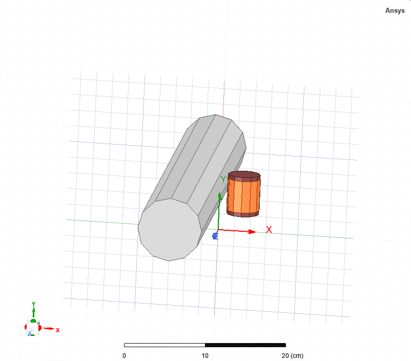
Current in the conductor is assigned as below
The coil terminal direction is assigned as below
I would like to do several parametric sweeps by changing the number of coil turns, diameter of the coil, length of the coil etc. and record the induced voltage (open circuit) and then output power of the assembly. Hence, I assigned a current type excitation to the winding, and set current to 0. Then when I perform the analyses, the induced voltage is negative. Here are my questions,
- According to lenz's law the induced voltage should oppose the magnetic flux created by the conductor which penetrate the core. But when the induced voltage is negative in this scenario.
- I tried using an external circuit to measure the voltage and current by attaching a resistor to the output of the coil. But when I do parametric sweeps, the coil resistance and inductance change. Is there any way to assign the values obtained from the matrix to resistors in the external circuit?Â
The analyses were done in eddy current mode. Any help is highly appreciated.Â
-
September 22, 2023 at 6:51 am
Reshmi Raghavan
Ansys EmployeeHello Dinu,
The induced voltage is coming up as negative becuase the current excitation direction specified is opposite to the one in which the current would flow .Â
Beucase of the magnetic field B the induced current in the coil would be in anticlock wise direction but the assigned direction is in clock wise direction. In order to represet this the induced voltage is coming up as negative component.
-
September 22, 2023 at 6:56 am
dinushaxdn
SubscriberHello Reshmi,
Thank you for your comment. But according to Lenz's law, the induced voltage should form opposing the magnetic field which caused it, right?Â
-
- The topic ‘Calculating the output power from a coil placed closer to a conductor’ is closed to new replies.
- Three-Phase Voltage Imbalances in dual stator electric generator
- Co-simulation in Q3D, Icepak – meshing problem
- Classic Icepak – clarifications on Boundary condition
- Link the Circuit to 3D Terminals
- Magnetic Dipole moment calculation
- Integration lines or U Axis Line for circular and rectangular ports
- Core Loss in ANSYS MAXWELL Eddy Current solution
- exporting and importing my Netlist for my external circuit
- Error of Metal Fraction in Icepak Classic.
- The unit of theta in Is*sin(2*pi*fre*Time+theta-2*pi/3)
-
4592
-
1494
-
1386
-
1209
-
1021
© 2025 Copyright ANSYS, Inc. All rights reserved.


