-
-
December 1, 2024 at 4:56 amtranvietducnguyenSubscriber
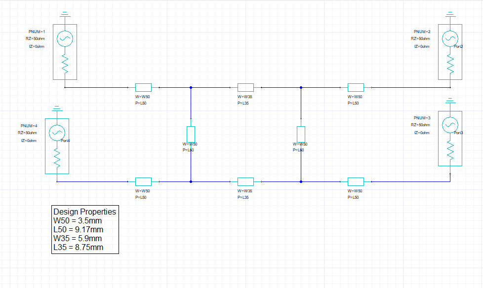
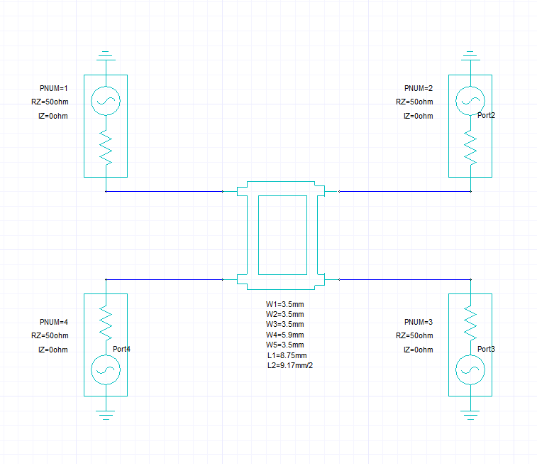
I am learning the course with the Branch line coupler in Lesson 2. After simulating the coupler in circuit, I use the circuit component provided within HFSS, where I put my optimized values for the coupler. The coupler I designed on Taconic RF-35 substrate, thickness of 1.52 mm, DK = 3.5. However, after I inserted all of the input parameters as shown in the tutorial video, I receive a message, which is shown below:
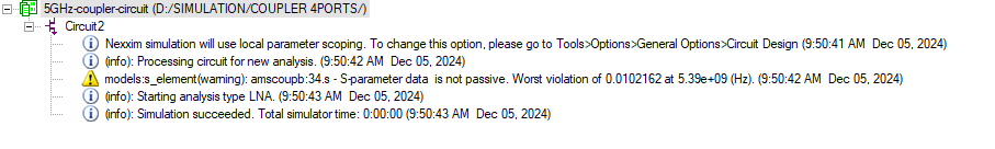
Coupler-5GHz-component (D:/SIMULATION/COUPLER 4PORTS/)
 Circuit1
  [info] Nexxim simulation will use local parameter scoping. To change this option, please go to Tools>Options>General Options>Circuit Design (11:52:42 AM  Dec 01, 2024)
  [info] (info): Processing circuit for new analysis. (11:52:43 AM  Dec 01, 2024)
  [warning] models:s_element(warning): amscoupb:11.s - S-parameter data  is not passive. Worst violation of 0.0102162 at 5.39e+09 (Hz). (11:52:43 AM  Dec 01, 2024)
  [info] (info): Starting analysis type LNA. (11:52:44 AM  Dec 01, 2024)
  [info] (info): Simulation succeeded. Total simulator time: 0:00:00 (11:52:44 AM  Dec 01, 2024)
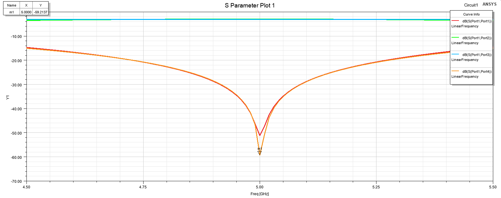
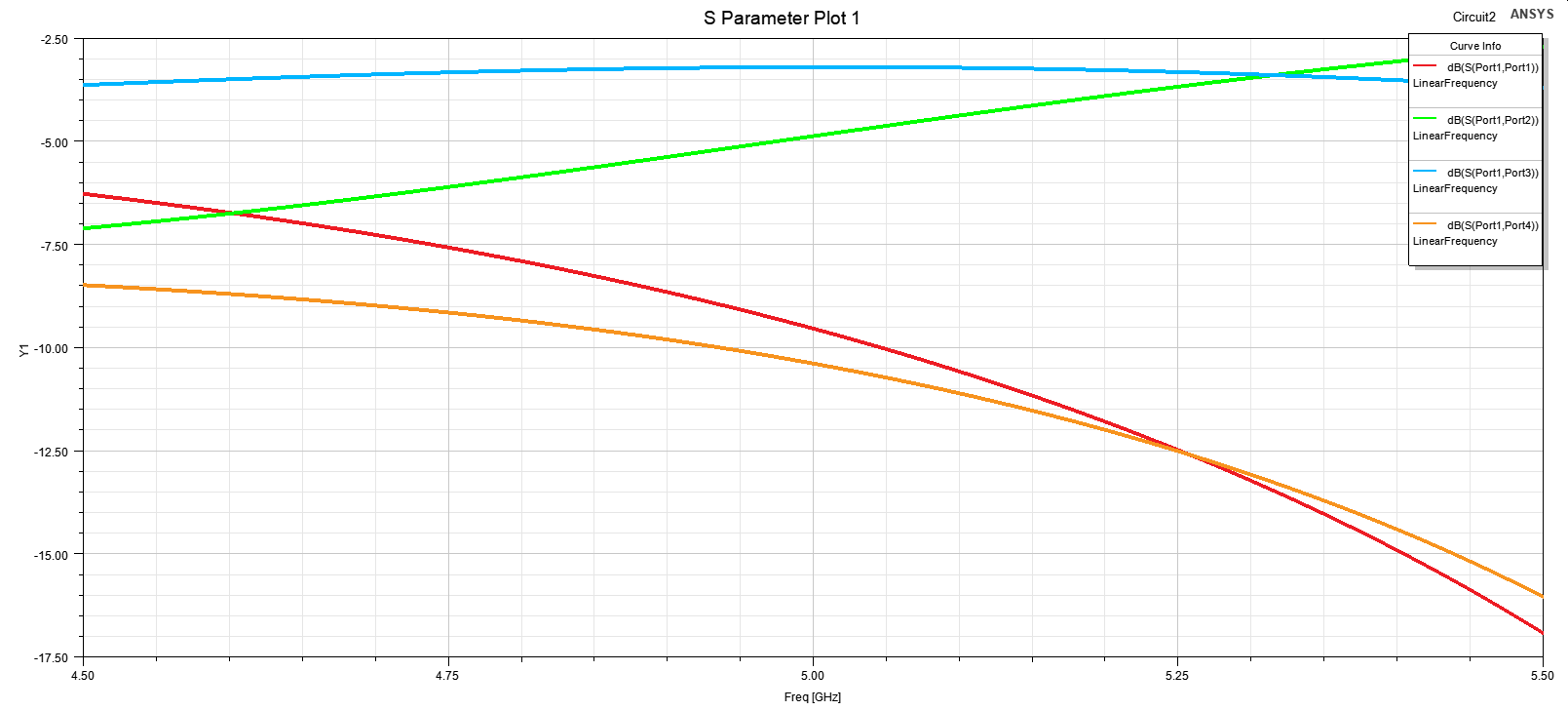
The results I obtained are not like what I got when I simulated with circuit component, which is clearly not as what shown in the video. Please help me out with this issue. Is there anything that I am missing while doing this simulation.
Thank you in advance.
-
December 4, 2024 at 6:22 pmPraneethForum Moderator
Hi,
Thank you for going through our AIC course and reaching out to the Ansys learning forum.
Please share the results and snapshot of the setup to help us serve you better.
 Best regards,
Praneeth. -
December 5, 2024 at 2:59 amtranvietducnguyenSubscriber
Thank you for responding me.
The images and their order I attached below.Firstly, I simulated with the schematic design. The desired frequency is 5 GHz. In the picture below, the parameters of each microstrip line have been optimized to produce a S11 dip at 5.0 GHz. You can see the performance at the second image.
In the 3rd image, I tried to use the Nexxim coupler component as described at the end of Lesson 2.Â
Â
After importing the same values as the schematic design and run the Analysis, I obtained this message.
Also, the S-parameter with Nexxim coupler is in the last image, which is not centered at 5.0 GHz
-
December 11, 2024 at 2:21 pmPraneethForum Moderator
Hi,
I have verified the circuit model at my end and I did not receive any such warning.
Regarding the offset, it is expected to shift to higher frequency when component is used as compared to the TRL model. Same is shown in the lesson video of the specified course. Try increasing the frequency range to see the full response.
Best regards,
Praneeth.
-
- You must be logged in to reply to this topic.
- HFSS Incident Plane Wave excitement mode
- How to calculate eddy and hysteresis losses of the core?
- Ansys Maxwell 3D – eddy current
- Simulation of capacitor combining eddy currents with displacement currents
- dq graph non-conformity
- Simplorer+Maxwell Cosimulation results and Maxwell results mismatch
- Parametrizing coil “terminals” with coil geometry
- Maxwell circuit – PWM
- Plotting Ex, Ey and Ez in vector forms individually
- Calculating E-field tangential to a 2D resonant structure on a sapphire chip
-
1882
-
802
-
599
-
591
-
366
© 2025 Copyright ANSYS, Inc. All rights reserved.