-
-
August 21, 2023 at 6:15 pm
sandrzyk
SubscriberHello everyone.ÂIm working on a project related to snowboard and its binding. I have created a model which can be seen below. Im analysing the behaviour while the force applied is a load of a rider. Red element can slightly rotate thanks to the blue pin, which allows the whole binding to rotate aswell. Green elements are made with elastic material, which are used to dampen vibrations.ÂWhat boundary conditions and where should be applied to the model? I was thinking about applying Fixed Support on the bottom surface of snowboard, elastic support on the top surface of green elements, force on the surface on red element, and remote displacement on blue and red elements (displacement x y z=0 and free rotations).ÂÂThanks in advance! -
August 22, 2023 at 2:04 pm
Ashish Khemka
Forum ModeratorHi,
I am not sure how a real application should work, but fixed support sounds fine when there is no motion for snow board. Why define elastic support for green elements? YOu can use contact instead. Remote displacement sounds fine. Try running a simulation to see the results and then try changing the conditions if the behavior is not as expected.
Â
Regards,
Ashish Khemka
-
August 22, 2023 at 3:43 pm
sandrzyk
SubscriberThis video at 0:36 shows how the mechanism works: Now Bindings 'Skate Tech' Explained - YouTube
My boundary conditions and results:
Im not sure if this is correct, stresses on snowboard are equal to 0. Perhaps contacts are defined incorrectly? They were automaticly created by ansys and they seemed fine (all are bonded).
Â
Â
-
-
August 24, 2023 at 3:48 am
Ashish Khemka
Forum ModeratorHi,
I saw the videos and based on the video I would suggest (you will have to take a final call) fix only the bottom face of the board, Use frictional contact between green pads and board. When you apply remote displacement then do you see rotation? One way may be to solve the model in 2 steps - in the first step apply the load at half the region of the red area (say toe region) and in 2nd step apply the load at half the region of the red area (heel region) and then you may see the rotation and also have a conservative design. Also, what if you model a dummy leg (rigid body) on the skate and then rotate it slightly (along with weight). In this scenario you will need to add additional contacts as well.
Â
Regards,
Ashish Khemka
-
August 25, 2023 at 7:23 pm
sandrzyk
SubscriberHi,
I did what you said, and it gave me great results! Pressure can be seen on the snowboard now. Ignore the mesh quality, for now im concentrated on correct interpretation of the mechanism.
I made a second analysis where I put additional force to the part on the right side with 3 holes in it. 50N in Y+ direction. These are the stress results:
I think the pads are behaving weirdly. I was thinking about placing remote displacement on the surface of pads and allowing rotation in Z only.
Also. thank you so much for your time and help!
Â
Â
-
-
- The topic ‘
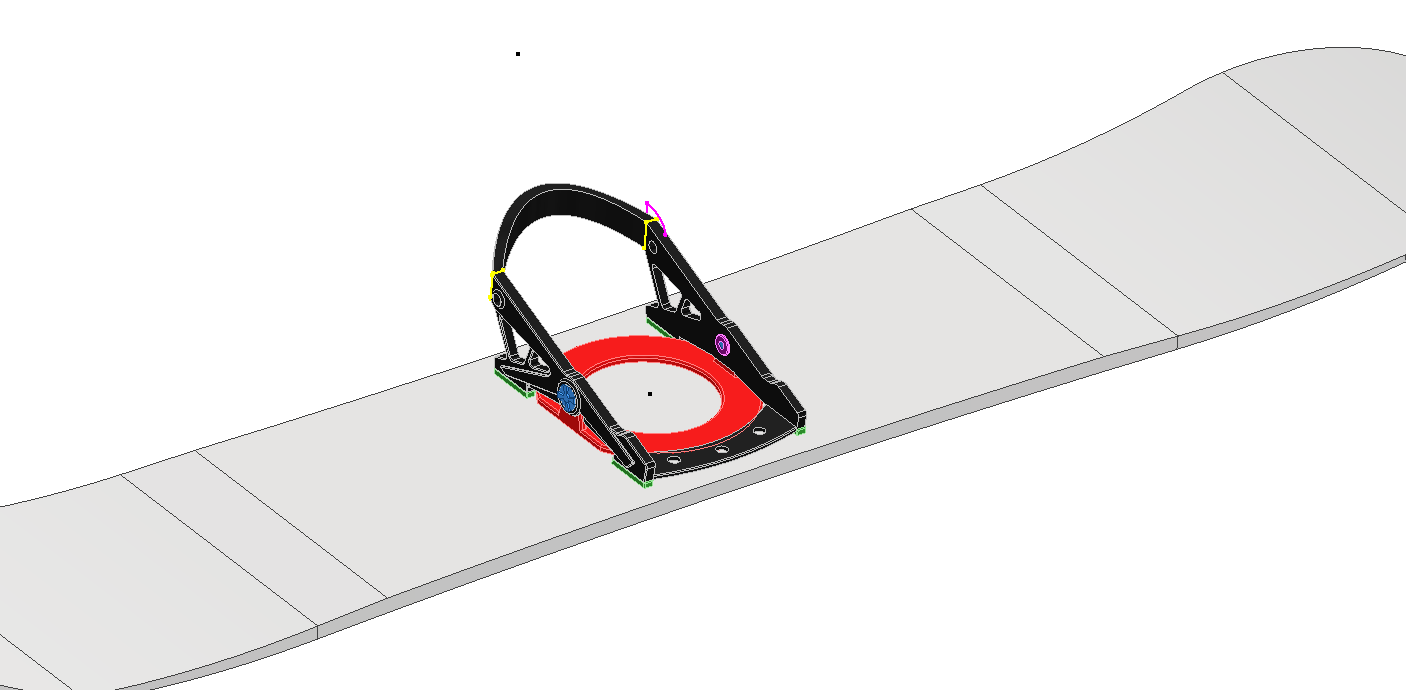
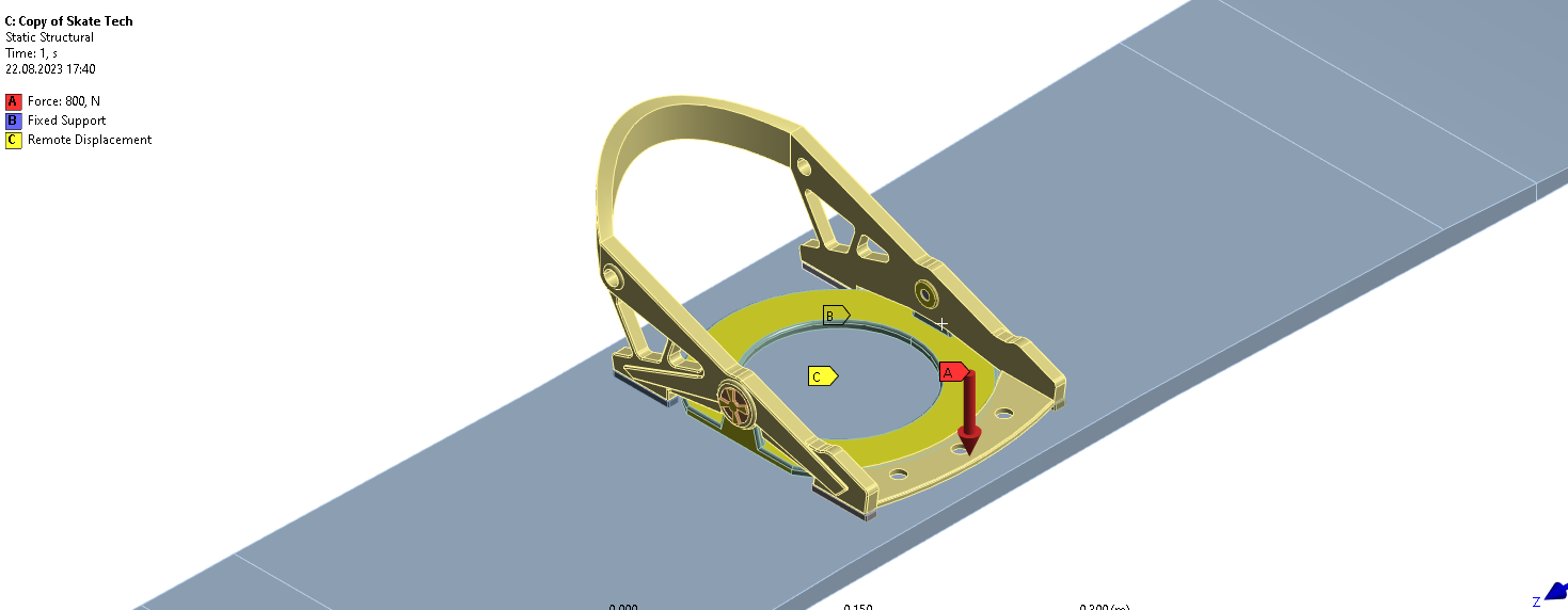
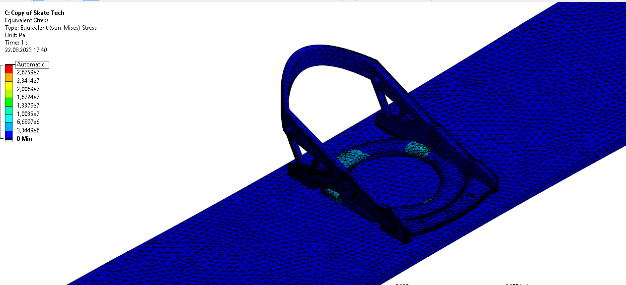
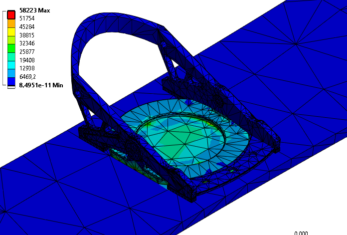
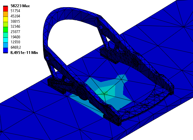
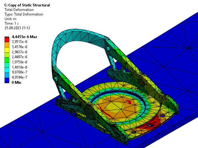
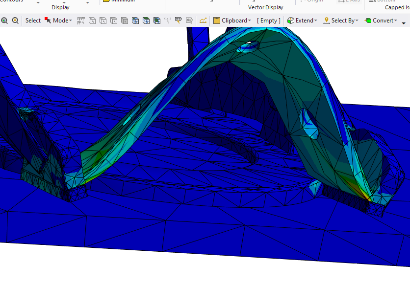
Boundary conditions on a snowboard and its binding’ is closed to new replies.
-
3492
-
1057
-
1051
-
965
-
942
© 2025 Copyright ANSYS, Inc. All rights reserved.