General Mechanical

General Mechanical

Topics related to Mechanical Enterprise, Motion, Additive Print and more.

Bonding of two shells with an offset

    • kaiyeungli
      Subscriber

      Hi there,


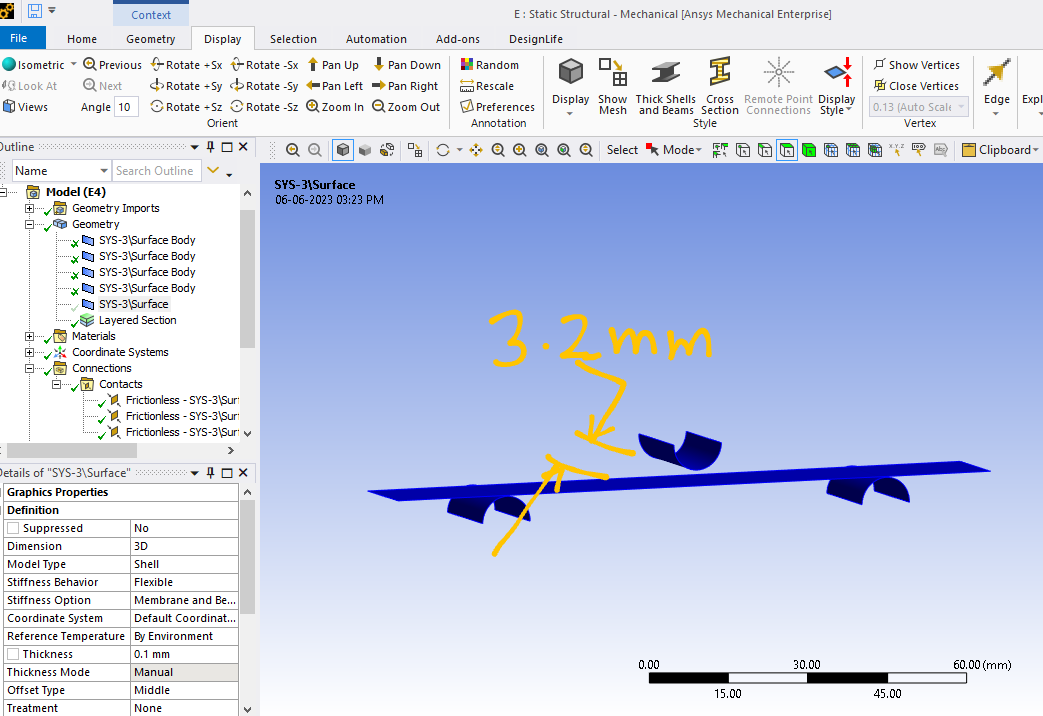
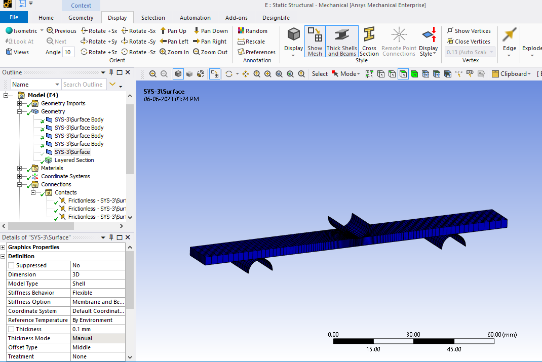
      I am having trouble understanding the results I am getting for a particular problem. I have two identical plates which I want to bond together and subject to bending. To simplify the model, I created mid-surfaces from the solids, and created a 'Bonded Contact' between the resulting shells. The SpaceClaim model I used is shown below. The solid plates are shown in green and their mid-surfaces are shown in red. My understanding is that the two bonded plates should now behave as one plate with twice the thickness. I want ANSYS to take into account the thickness of the shells when creating the contact - the bond takes place in the plane which is mid-way between the two shells. 


      The SpaceClaim model of the two plates, which are solids (green), and their mid-surfaces (red)


      The problem is that the results from a simply supported beam load-case do not match with my calculations or my solid model. Results from my solid model do match my calculations.


      The 'Contact' settings I used are shown below. I think that I chose the appropriate 'Contact Shell Face' and 'Target Shell Face' (they face each other), and I also set the 'Shell Thickness Effect' as 'Yes'.


      Am I doing something wrong here? Do bonded shells have to be coincident to be modeled properly?  


      Any help would be appreciated. Please let me know if this question has already been answered or if I should attached my model.


      I have also read the article: "BONDED CONTACT BETWEEN SHELL FACES IN ANSYS® MECHANICAL (WORKBENCH) V14.5" by Simutech.


      Thanks in advance.

    • Sandeep Medikonda
      Ansys Employee

      Insert an Initial Contact Tool and check the contact status. You might have to adjust the pinball radius. Please see this discussion and this article.


      I would personally recommend using shared topology if you want the bodies to act like one.


      https://www.youtube.com/watch?v=h43E1YO1LiM


      Regards,
      Sandeep
      Guidelines on the Student Community

    • jj77
      Subscriber

      When you do this on the finite element level, you just need to have two overlayed plate/shell element on top of each other, and then offset them as required. Very easy, but in WB, not sure how to do it. I would imagine using two faces on top of each other, then offset as required (half thickness up or down respectively) and then use merge nodes, to get overlayed plate/shell elements as explained in my first sentence. This is more appropriate and commonly used in structural engineering (e.g., double reinforced floor slabs) than having a contact between the plates. This approach was used below, giving same results as other FEA package (Strand7), so it is OK.


      One can also use multi layered shells, used for laminates, with two plies.


      Bonded contact works though, as mentioned use a large enough pinball region, and use a MPC formulation (basically connects umatched meshes).

    • kaiyeungli
      Subscriber

      Thank you for response and advice. I am using this problem as a test for a much more complex model where, for meshing purposes, I feel it's best not to share the topologies and use a bonded contact instead. The meshes have to be quite different sizes.


      I checked 'Initial Information' (shown in the image below). The contact status is 'Closed'. The 'Geometric Gap' is 1.79 mm (thickness of the plates, an arbitary number), but the 'Gap' is 0. Interestingly, the 'Gap' is 0 even when 'Shell Thickness Effect' is turned off.


      .'Initial Information' for bonded contact


      For reference, each plate is 1.79 mm thick, 20 mm wide and 120 mm long, made of structural steel. I am simply supporting both ends and applying 100kPa of pressure on top. Deflection in the middle should be 0.353 mm, but its 1.42 mm.

    • peteroznewman
      Subscriber

      I have done a similar test to the one you are describing to learn how bonded contact between two strips of steel, each of thickness t, could replicate the bending of a single body of thickness 2t.


      There are five Formulation types, though I would exclude Beam. I believe MPC offers the closest representation of a single body solid, but you should do your own evaluation.


      When you say deflection in the middle should be 0.353 mm, where did that number come from?


      Do you have large deflection turned on?


      When I was studying deformation of a honeycomb sandwich structure, I was able to adjust the shear modulus of the core in order to tune the model to match the experimental data.


    • kaiyeungli
      Subscriber

      Hi Peter,


      Thanks for your help.


      The number 0.353 mm came from beam theory - the equation for maximum deflection of a simply-supported beam under a uniformly-distributed load was taken from this website https://structx.com/Beam_Formulas_001.html.


      I did not have large deflection turned on.


      I believe that changing the formulation to MPC is the solution because that resulted in a deflection 0.354 mm, which is close enough. Am I correct in thinking that the problem with an Augmented Lagrange formulation (program controlled default) was that the two surfaces were essentially connected via springs, meaning that there would always be some relative movement between the two surfaces in the tangential direction? MPC on the other hand, directly ties the DOF's of nodes on both surfaces.


      Thanks again.

    • kaiyeungli
      Subscriber

      Hi Peter,


      The number 0.353 mm came from beam theory - the equation for maximum deflection of a simply-supported beam subjected to a UDL taken this website. 


      I did not have large deflection turned on.


      I believe that changing formulation to MPC is the solution. When I do that, I get a deflection of 0.354 mm. Am I correct in thinking that the problem with an Augmented Lagrange formulation (program controlled default) was that, because it created a spring between the surfaces, there was a small amount of relative tangential movement? Like you said, MPC is a more accurate formulation in this case because the DOF's of nodes on both surfaces were tied. However, I am surprised that the difference in deflection was so large between the two formulations.


      Many thanks,


      Kai-Yeung

    • Ajay Kumar
      Subscriber

      Hi There,


      I am facing a similar problem in 3- point bending test using layered section having thickness 3.2 mm as mentioned in image.(I have to fill this gap with layered section).

      To make connection among layered section and upper roller, target or contact require surface or face on the layered section but, I'm unable to do so.

      So, could you please tell me how to make connection between layered section and roller face.


      Also kindly suggest me which connection should I make in these rollers in order to conduct 3 point flexural test ASTM D790.  Because I'm doing this first time.


      Thank you!


      With Regards,

      Ajay Kumar 

Viewing 7 reply threads
  • The topic ‘Bonding of two shells with an offset’ is closed to new replies.