
TAGGED: beams-and-shells, bolt, integration-point, shell-elements
-
-
November 9, 2020 at 11:16 am
bokaJ
SubscriberDear ladies and gentleman.
I have a problem with my structural analysis.
I want to simulate 2 metal plates which are bolted together, as you can see in the following picture.
November 10, 2020 at 4:29 ampeteroznewman
SubscribernOpen the Geometry in SpaceClaim, go to the Workbench tab and use the Share Button. That will make the circular edge on the outside of the face used to represent the bolt head to share nodes with the rest of the surface of the plate. That will let you delete all the Bonded Contact, which will help simplify your model.nDid you watch my video series? /forum/discussion/1217/bolt-pretension-clamps-two-plates-togethernNovember 11, 2020 at 11:09 amSubscriberThank you very much for your answer.nThe deformation looks a lot smoother, as you can see in my following picture. Alos the stress peaks at the bonded sections are gonen But there is still a big difference to the normal stress of the 3D modell as you can see in the following picture.n
 I have turned lager deflection off in both cases, so I can better compare it to my hand calculation.nThe direction of my forces are definded by components.nYes, I have already seen your videos.nThank you therefore, they are great!! I built my modell like yours.Could it be possible, that I need more integration points in shell thickness direction?.Thank you very much for your helpnBest regardsnbokaJnn
November 21, 2020 at 2:50 pmSubscribernThe solid model is built along the X axis while the shell model is built along the Z axis. Can I trust that the geometry, loads and supports are identical?nOnce two models are laid out with the same conditions, the difference between the stress in the shell elements should be comparable to the solid elements.nNovember 23, 2020 at 9:35 amSubscriberThank you for your answer sir.nnI am sorry, that it is a little bit confusing because the coordinate system is not the same in the two examples.nSo i did I did it again and used the same coordiante system therefor.nAbove you can see the dimensions of the model. I prooved it again, the dimensions of the two models are the same.n
I have turned lager deflection off in both cases, so I can better compare it to my hand calculation.nThe direction of my forces are definded by components.nYes, I have already seen your videos.nThank you therefore, they are great!! I built my modell like yours.Could it be possible, that I need more integration points in shell thickness direction?.Thank you very much for your helpnBest regardsnbokaJnn
November 21, 2020 at 2:50 pmSubscribernThe solid model is built along the X axis while the shell model is built along the Z axis. Can I trust that the geometry, loads and supports are identical?nOnce two models are laid out with the same conditions, the difference between the stress in the shell elements should be comparable to the solid elements.nNovember 23, 2020 at 9:35 amSubscriberThank you for your answer sir.nnI am sorry, that it is a little bit confusing because the coordinate system is not the same in the two examples.nSo i did I did it again and used the same coordiante system therefor.nAbove you can see the dimensions of the model. I prooved it again, the dimensions of the two models are the same.n n
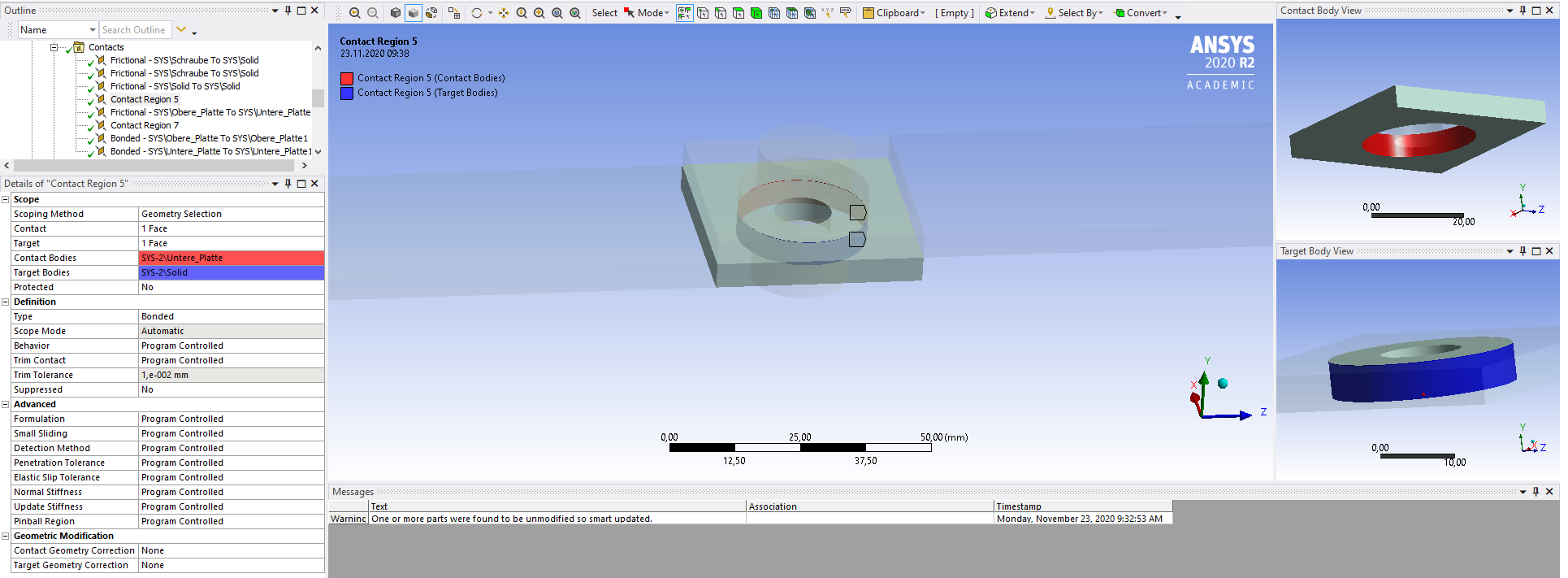
n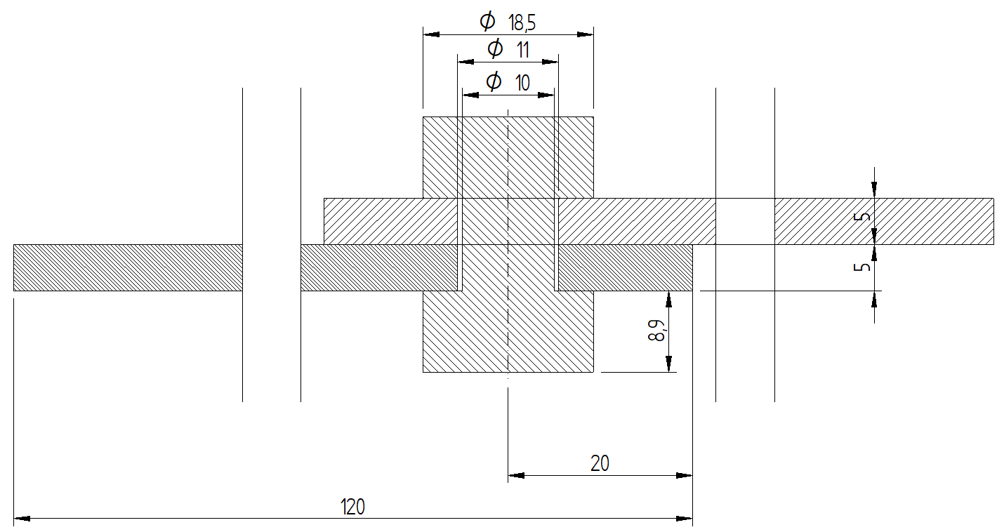 At first you can see my settings for the solid model:nI did not share the topology in the geometry, So I can give every sinlge subsection of a part a mesh which fits best. ncontacts:n
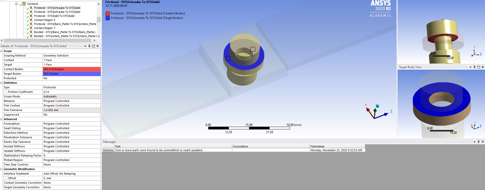


 n
n n
n
 n
November 23, 2020 at 9:39 amSubscriber_____________________________________________________________________________________________________________________________________________________________________________________nshell and beam model:ndimensions:n
n
November 23, 2020 at 9:39 amSubscriber_____________________________________________________________________________________________________________________________________________________________________________________nshell and beam model:ndimensions:n
 nbeam settings:n
 n
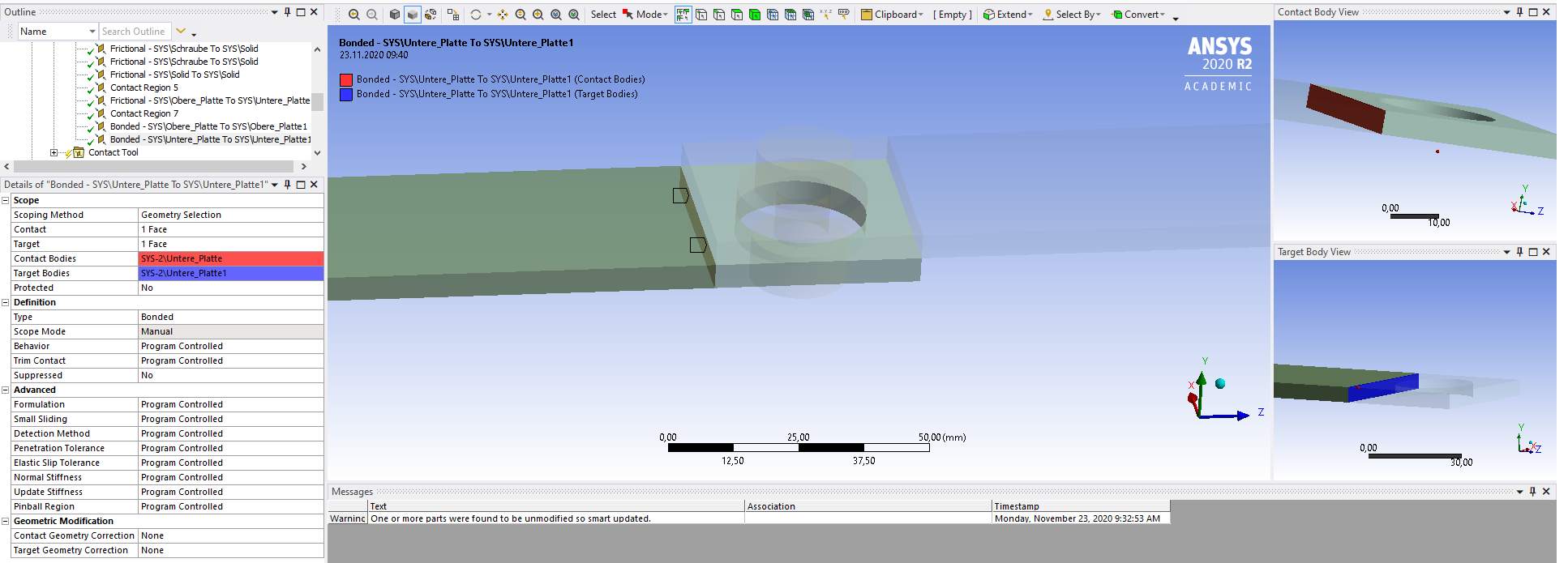
n nContacts:n
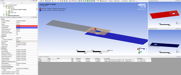 n
n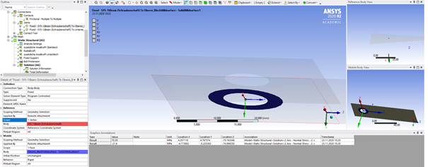 n
n n
n nIn this case I shared the topology in the geometry tool: n
 nmesh:n
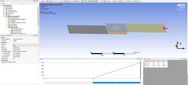
 November 23, 2020 at 9:40 amSubscriberforces and boundary conditions:n
 n
n
 nn
nn nn
nn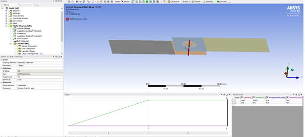 nanalysis settings:n
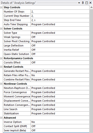 n
n nnnormal stress in z-direction:n
 nn
November 23, 2020 at 9:58 amSubscriberThe result of the 3D analysies is close to my hand calculation(25N/mm^2, 175 N/mm^2, -125 N7mm^2). But the result of the beam and shell model is far away from the others.nnIf I turn on large deflection I get the following results. In this case these two reluts are in my opinion also too fare away from each other.n
nn
November 23, 2020 at 9:58 amSubscriberThe result of the 3D analysies is close to my hand calculation(25N/mm^2, 175 N/mm^2, -125 N7mm^2). But the result of the beam and shell model is far away from the others.nnIf I turn on large deflection I get the following results. In this case these two reluts are in my opinion also too fare away from each other.n
 November 23, 2020 at 10:00 amSubscriberI hope that I provided all the information to you which you need to help me.nIf you need further information, please ask me.nnThan you very much sir! nNovember 23, 2020 at 11:03 amSubscribermesh:n
 nn
nn nn
nn nnanalysis settings:n
 nnnormal stress in z-direction:n
 The Ansys Learning Forum is a public forum. You are prohibited from providing (i) information that is confidential to You, your employer, or any third party, (ii) Personal Data or individually identifiable health information, (iii) any information that is U.S. Government Classified, Controlled Unclassified Information, International Traffic in Arms Regulators (ITAR) or Export Administration Regulators (EAR) controlled or otherwise have been determined by the United States Government or by a foreign government to require protection against unauthorized disclosure for reasons of national security, or (iv) topics or information restricted by the People's Republic of China data protection and privacy laws.
Please Login to Report Topic
Please Login to Share Feed
Edit Discussion
[bingo_chatbox]The Ansys Learning Forum is a public forum. You are prohibited from providing (i) information that is confidential to You, your employer, or any third party, (ii) Personal Data or individually identifiable health information, (iii) any information that is U.S. Government Classified, Controlled Unclassified Information, International Traffic in Arms Regulators (ITAR) or Export Administration Regulators (EAR) controlled or otherwise have been determined by the United States Government or by a foreign government to require protection against unauthorized disclosure for reasons of national security, or (iv) topics or information restricted by the People's Republic of China data protection and privacy laws.
-
