Ansys Assistant will be unavailable on the Learning Forum starting January 30. An upgraded version is coming soon. We apologize for any inconvenience and appreciate your patience. Stay tuned for updates.
General Mechanical

General Mechanical

Topics related to Mechanical Enterprise, Motion, Additive Print and more.

Bolt pretension in a nut connection

    • laiosi.virgo
      Subscriber

      Hi everyone,
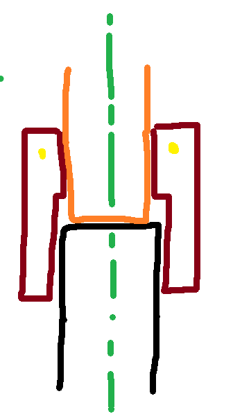
      I want to study the behavior of this fluidic threaded joint. It consists of a male threaded element (black) and a sort of bushing (orange, no threaded) that are linked to two different tubes. For locking the connections, I use a nut (red) with a retaining wire (in yellow) that blocks axiallly the nut (the axis of revolution is the green one). I apply a certain preload to the nut, that compresses the other two elements in order to guarantee the retention capability of this fluidic joint.

      As you can see from the image, this nut is divided in a threaded portion and non-threaded one, that interfaces respectively with black and orange element. So, in this application the element that is pulled in traction is the nut, effectively. In normal cases of bolted joints, I notice that the bolt is in traction.

      How can I set Bolt Pretension for this application? My doubt is that Ansys could look the threaded face of the nut as a sort of "threaded hole", so he will fail to apply the Bolt Pretension. I can study this joint both in 3d or axysimmetric 2d geometry, which system do you reccomend to use to me?

      Thanks


    • peteroznewman
      Subscriber

      Build a 3D model if you want to apply a bolt pretension load. There is no doubt that bolt pretension works on a pipe section of geometry. Create a plane at the end of the black pipe and use that plane to split the cylindrical faces of the nut to separate the face that will engage with the black pipe from the short length of the inner face of the nut before the inner diameter change.  Select this short length to apply the bolt pretension. Split the outer cylindrical face at the diameter change. Use multizone meshing and you should be able to get hex meshing on the entire nut.

      To save computation solve time, you can use two planes through the axis of symmetry and cut the model twice and keep a quarter model.  You can have an acute angle between the planes to make an even smaller model.  The cut faces of all the parts require either a Symmetry region with the appropriate normal selected, or the equivalent Displacement BC.

      The crude sketch doesn’t show the details of how the seal is created. Do you have a more detailed cross-section that shows how the seal is created?  Is the tube flared after the nut is slipped over the tube to create a JIC or SAE type of fluidic seal?

Viewing 1 reply thread
  • You must be logged in to reply to this topic.
[bingo_chatbox]