-
-
February 21, 2024 at 4:54 pm
deepesh.p.gurdasani
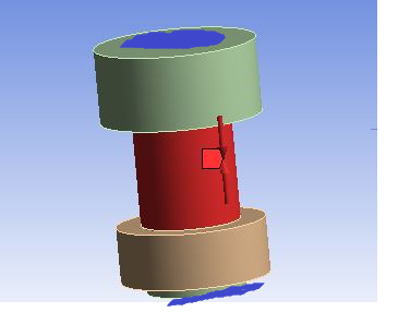
SubscriberI am attaching images of Bolt pretension used in a simple geometry.
Bolt, Nut, two plates
The dimensions are random.
Contacts: Projected bolt head on upper plate, nut on bolt shank, nut on lower plate.
Bolt head to upper plate - frictional
nut to bolt shank - bonded
nut to lower plate - frictional
between plates-frictional
bolt shank to first plate clearance hole - frictionless; bolt shank to second plate clearance hole - frictionless
gave fixed support at side surface of one plate, it showed 'Magnitude exceed' error. Tried with solver pivot switching to OFF, weak springs ON, Large deflection ON, increased substeps but still it wasnt converging.
So, gave fixed support to second plate's side surface also. It converged but the stress and deformation is unusually high.
Can anyone guide where I am making mistake?
-
February 22, 2024 at 9:30 am
Aniket
Forum Moderatorfew suggestions.
- Try with actual dimensions and actual loads. (or something near actual instead of random)
- Change Bolt head to upper plate and nut to lower plate to bonded instead of frictional
- try to use nonlinear material properties
-Aniket
-
February 22, 2024 at 1:34 pm
deepesh.p.gurdasani
SubscriberThanks for reply.
- How would that matter? as the preload applied is 1000 N and there is not much complexity. Tried with some proper diameter like M6. Results vary but unsually high such as shown in images.
- Tried this too.
- Shouldn't it work for Stainless Steel ? normally ?
Could it be because of Frictional contacts being used ? but in reality also, we take it as frictional only, right ?
-
February 23, 2024 at 9:29 am
Aniket
Forum Moderatorjust confirming that you are seeing an issue even when the two contacts are made as bonded instead of frictional? Yes, Ideally it would be frictional, But as there will be next to none sliding, in most cases it can be assumed bonded.
Another technique would be using a very small bolt pretension in the first step, to establish all the contacts, and once it is done, then ramp that up to the actual value in the second step.
-Aniket
-
March 4, 2024 at 6:54 pm
deepesh.p.gurdasani
SubscriberBonded or frictional, both are giving more or less same results. - Fixed two opposite sides of both the plates to check if there is any change but no change.
-
-
February 22, 2024 at 2:17 pm
Gary_S
Ansys EmployeeHi. For the bolt load, try using an adjustment (length) insead of a force.
Gary -
February 22, 2024 at 3:17 pm
deepesh.p.gurdasani
SubscriberTried with adjustment (length). Its not converging
-
February 22, 2024 at 8:19 pm
Gary_S
Ansys Employee- Try bonding all contacts just to see if you get a result.
Gary-
March 4, 2024 at 6:51 pm
deepesh.p.gurdasani
Subscriber1) Tried with all bonded.
2) Tried with 4 steps - step 1 - bolt preload 10 N, 2nd step - 100 N, 3rd step - 1000 N and 4th step 'Lock'.
Above trials gave more or less same result only.
-
-
March 4, 2024 at 7:47 pm
Gary_S
Ansys EmployeeHello
Can you show us where you are applying the Bolt Pretension load ?Gary
-
March 5, 2024 at 4:04 pm
-
-
March 5, 2024 at 8:22 pm
Gary_S
Ansys EmployeeDo the rectangular plates have contact on the same face as the bolt load?
Care should be used when applying a Bolt Pretension boundary condition to a cylindrical face that has bonded contact. There is a possibility that if you apply a Bolt Pretension boundary condition to a cylinder that had a bonded contact region, the bonded contact will block the ability of the Bolt Pretension to deform properly.
-
March 6, 2024 at 2:30 pm
deepesh.p.gurdasani
SubscriberYes the rectangular plates have 'frictionless' contacts with the bolt shank ((Same area where the bolt preload is applied)).
The bolt preload is applied only on the area shown in image so that it doesnt interfere with the bonded contact.
-
March 6, 2024 at 1:37 am
deepesh.p.gurdasani
SubscriberYes the rectangular plates have 'frictionless' contacts with the bolt shank (Same area where the bolt preload is applied).
The bolt preload is applied only on the area shown in image so that it doesnt interfere with the bonded contact.
-
March 6, 2024 at 2:41 pm
Gary_S
Ansys EmployeeChange all bodies to Structural Steel material
Add a Fixed support to the top (or bottom) circular face. -
March 7, 2024 at 6:24 pm
deepesh.p.gurdasani
SubscriberAll bodies changed to Structural Steel material.
Added a fixed support at cicular face of plate (Removed other fixed supports).
Deformation is quite less. the bolt shank doesnt go on extending as it was happening earlier but the stress remains the same at the below circular surface area of second plate.
I doubt if this is a correct way(Fixing a inner circular surface of either one of plates - as this will not let the bolt apply compression on both the plates as one of the plates would get fixed).
-
March 7, 2024 at 6:37 pm
-
March 7, 2024 at 6:53 pm
deepesh.p.gurdasani
SubscriberThe result remains same. Although deformation changes by very small amount but stress is near to same (I mean in the same range).
-
March 7, 2024 at 7:00 pm
Gary_S
Ansys EmployeeIs the deformation still excessive 5e5 mm ?
-
March 20, 2024 at 6:05 pm
deepesh.p.gurdasani
SubscriberHi Gary, any further guidance in this regard?
-
-
March 8, 2024 at 4:37 pm
deepesh.p.gurdasani
SubscriberNo. The deformation is in the range 0.01 to 0.03 approx. after giving fixed support to upper face of bolt head.
-
March 18, 2024 at 3:18 pm
deepesh.p.gurdasani
SubscriberAny further guidance in this regard ?
-
- The topic ‘Bolt pretension giving unusual results’ is closed to new replies.


-
4934
-
1638
-
1386
-
1242
-
1021

© 2026 Copyright ANSYS, Inc. All rights reserved.


