TAGGED: ansys-mechanical, displacement, remote-force, remote-point
-
-
December 3, 2024 at 11:00 am
fsvensen92
SubscriberHi
I have a some solids which all have a face in the same YZ plane. I want apply a pulling force in the X direction to the faces and study the displacement. I have created a rigid remote point scoped to all the faces and applied a force to the point.However I notice some rotation of the faces which I want to eliminate, the faces should only have translation in the X direction. What would be the correct approach to achieve this?
My ideas currently are:
- Apply a displacement to the faces directly, with only the X DOF free
- Apply a remote displacement to the remote point
Is there a difference between the two?
Thanks! -
December 4, 2024 at 10:00 am
mohan.urs
Ansys EmployeeHey,
Applying a displacement directly to the faces with only the X DOF free would constrain the faces to move only in the X direction, without any rotation. This method directly restricts the movement of the nodes on the face to the specified DOF.
On the other hand, using a remote displacement involves defining a remote point and applying the displacement to this point. Remote points are particularly useful when you want to apply a displacement to the center of a face while allowing rotational freedom, or when you want to apply a force at a location away from the mesh without over-constraining the system.
In your case, since you want to eliminate rotation completely, applying a displacement directly to the faces with only the X DOF free might be the more straightforward approach. This would ensure that the faces are constrained to translate only in the X direction without any rotation.If you need more insights on this, I would suggest that you explain the setup and your end goal with some snipshots.
Regards,
Mohan Urs-
December 10, 2024 at 9:51 am
fsvensen92
SubscriberHi Mohan
Thanks for your reply.
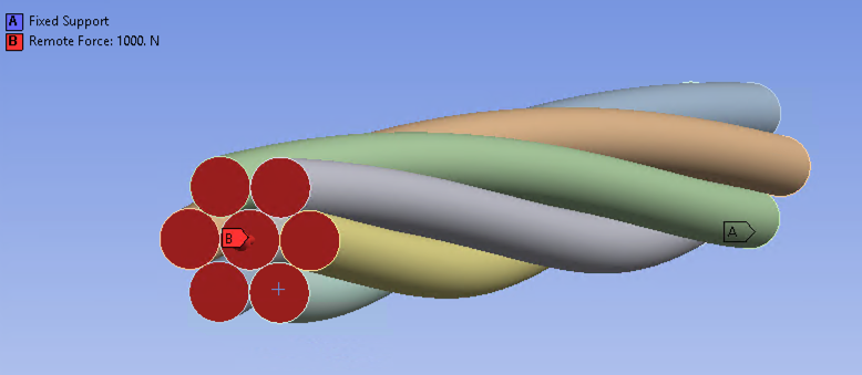
This is my base setup.
Fixed support on one end, remote force thorugh a rigid remote point on the other. I want to disallow rotation on the faces where the remote force is applied.
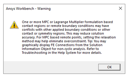
I am also getting warnings about rigid body motion and the solver is adding weak springs, any idea what is causing this?
-
December 10, 2024 at 11:50 am
mohan.urs
Ansys EmployeeHey,
So the direct displacement should work for you.
And regarding the warning you can check the weak spring forces that are being generated. If they are low it won't be a problem.
To check what is causing that error you can check out this course https://innovationspace.ansys.com/courses/courses/prevent-rigid-body-motion-in-contact/Regards,
Mohan Urs -
December 10, 2024 at 12:24 pm
-
-
-
- You must be logged in to reply to this topic.


-
4858
-
1587
-
1386
-
1242
-
1021

© 2026 Copyright ANSYS, Inc. All rights reserved.


