-
-
March 25, 2023 at 1:02 pm
javat33489
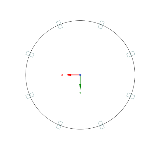
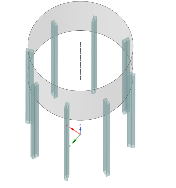
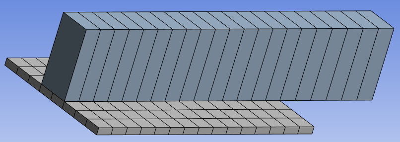
SubscriberHi all. I have a cylinder made of steel rings, they are held by beams at the bottom on two rings. The structure is several meters high. I solve a problem in static analysis using beams and shells. During the creation of beams and shells, I had questions.
- When we make beams and shells, we attach a strip (beam) to the shell in SPACE CL. Thus, if you build a mesh, then the beam will be in the middle of the sheet (to which it was drawn). Further, in the MODEL section in the neometry tab, you can assign an offset to the beam so that the beam is attracted to the sheet only by the wall, does this affect the calculation or only the visual?
2. Before all the sheets (rings) and beams were converted into beams and shells, there was a body (volume extract) inside the cylinder, which simulated the filling of this cylinder with a medium. When I made the rings of the cylinder into shells, the body of the medium became smaller in diameter and I had to double it up to the shell. Does it affect the calculation? This is right?
-
March 25, 2023 at 6:21 pm
peteroznewman
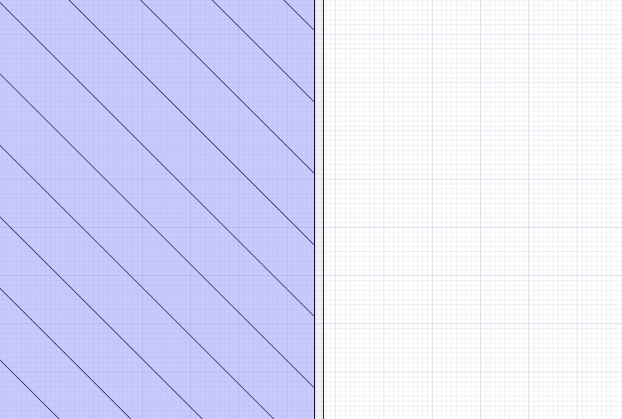
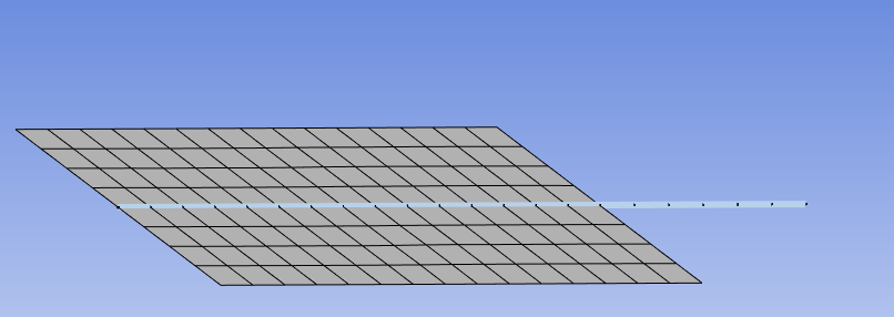
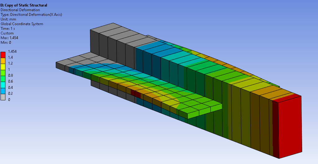
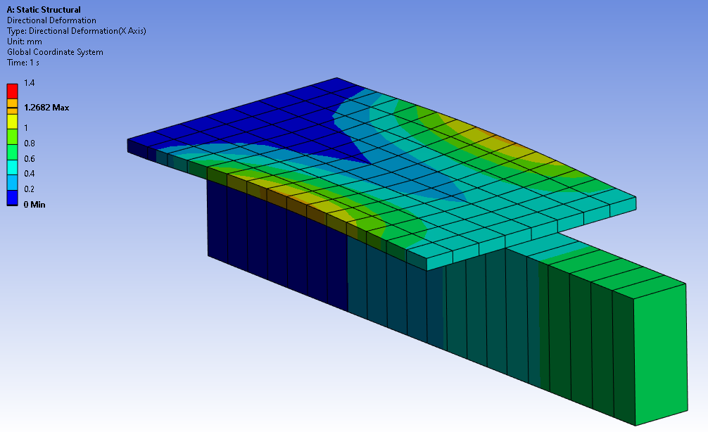
Subscriber1. Here is a beam and surface that share topology from SpaceClaim. The nodes along the beam and surface are shared which simulates a beam with a full length weld to the surface.
The beam and surface are manually offset in Mechanical to give the proper appearance, which does affect the calculation.
2. When the solid cylindrical wall has a Midsurface operation, that pulled the surface away from the solid on the inside. The solid on the inside will not be connected to the wall once the geometry is opened in Mechanical.
-
March 25, 2023 at 7:29 pm
javat33489
Subscriberwhich does affect the calculation.
this is very bad. But how do they influence? I made a test model, with offset and without the result was the same
When the solid cylindrical wall has a Midsurface operation, that pulled the surface away from the solid on the inside. The solid on the inside will not be connected to the wall once the geometry is opened in Mechanical.
- this is my question, do I need to extend it to the shell? for example, a pull tool in the SC.
-
March 25, 2023 at 9:35 pm
peteroznewman
Subscriber-
March 26, 2023 at 10:21 am
-
-
March 26, 2023 at 10:18 am
javat33489
SubscriberThanks a lot!
-
March 26, 2023 at 12:24 pm
peteroznewman
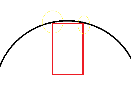
SubscriberA beam element is a line, so it only touches the cylinder at that line if you use Shared Topology. This is generally an acceptable approximation when the beam width is a small fraction of the cylinder circumference.
If the beam width is relatively large, then you could cut the cylinder on each face of the beam, leave the beam at the true beam centroid with no offsets and use Bonded Contact to connect the beam to the two lines on the cylinder. That would be like two weld lines, one on each side of the beam.
-
March 26, 2023 at 6:06 pm
javat33489
SubscriberThanks, I'll think about it and try
-
-
- The topic ‘Beams and shell issues’ is closed to new replies.


-
4959
-
1644
-
1386
-
1242
-
1021

© 2026 Copyright ANSYS, Inc. All rights reserved.

