-
-
June 23, 2021 at 10:48 pm
PaulaAmir
SubscriberI have been working on skateboard chassis of An EV and I have done Static Structural analysis on the chassis first then I have done Modal analysis to be as input to the the transient analysis. The problem here regarding the transient analysis first I have done quarter car model using MATLAB using a bump to obtain the acceleration from the suspension system second I have my fixed Support in the place of the four wheels of the chassis done in the modal analysis third I put the Acceleration obtained from MATLAB on the two front wheels of the chassis and the two rear wheel is fixed and I have done it using Base excitation. The problem here is the values of the Stress is too large. Is the problem regarding the settings of Ansys specifically The acceleration settings regarding the The base Excitation and absolute result Or I have read about damping ,stiffness, mass coefficient so applying them will make difference in the values of stresses . or another thing should be taken into consideration
It will be helpful is someone could help As this my Bachelor Project.
Thanks in Advance.
June 24, 2021 at 12:35 ampeteroznewman
SubscriberHello Paula I can help with your project, and others may reply also. Please post some images of the model.
You say you have created a quarter car model in MATLAB, which implies just one wheel. I would like to know what you learned from that.
You have also looked at a Modal analysis and you say you fixed the rear wheels. What did you do with the front wheels? Please show the constraints you used in your Modal analysis. What was the total mass in the model? How many springs did you include in the model? What was the spring rate? Did you use any Joints in the model> Please show them.
Let's just focus on creating a valid Modal analysis before we worry about the base excitation.
Regards Peter
June 24, 2021 at 12:44 amPaulaAmir
SubscriberI did not get you by ( what you learned from that ) i have done the quarter car model using Using picture 1
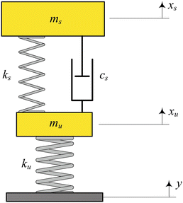 The Y in the Above picture related to bump I have fixed both front and rear wheels and apply the Base excitation on the two front wheel This is the picture for the four Fixed support for modal Analysis
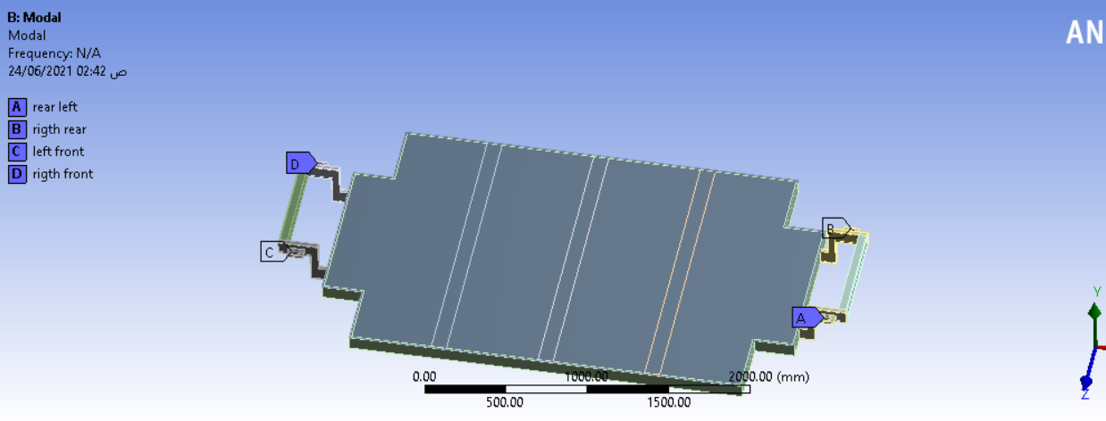
The total mass of the chassis was 469 kg I have used two springs Sprung mass stiffness ,Unsprang mass stiffness , I did not know the meaning of joints in the model And I have not include the spring rate
June 24, 2021 at 12:59 ampeteroznewman
SubscriberThanks for the images So in MATLAB, you have a base, which is the road.
You have a mass Mu, is that the wheel?
You have a spring Ku, is that the spring rate of the tire?
You have a mass Ms, is that the mass of the car?
You have a spring Ks, is that the spring rate of the suspension?
What output did you get from this MATLAB model?
I see you have a Modal analysis, and it looks like you have a frame with the four corners. That frame could represent the Ms from the MATLAB model. While you can run a Modal analysis on the frame to find how that might vibrate, that doesn't correlate with the MATLAB model.
If you want an Ansys Modal model that agrees with the MATLAB model, then you want to add a mass at each corner to represent each wheel. There will need to be either a suspension linkage between the wheel and the frame or an ANSYS Joint and then you can add a Spring/Damper to represent Ks from the MATLAB model.
June 24, 2021 at 1:18 amPaulaAmir
SubscriberMu is the mass of the wheel and suspension System yes
Ku is the Spring Stiffness for the chassis
MS quarter the mass of the Car
Ks is the spring Stiffness of the Suspension
The output Acceleration in the next graph
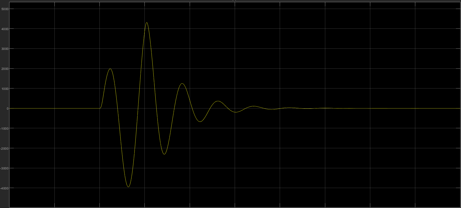 the maximum point is Almost equal to 4308 mm/s^2
you mean that I should add the mass Mu in the four corners in Ansys , I did not understand you in the part of the Suspension Linkage between Ansys and matlab
June 24, 2021 at 1:49 ampeteroznewman
SubscriberIf your goal is to reproduce in ANSYS what you did in MATLAB, then you need the same things, a mass for the wheel and a spring between the wheel and the car and a spring between the wheel and ground.
In MATLAB, you have a 1D model, so you don't need to worry about the 6 Degrees of Freedom (DOF) that each body has, but in a 3D model in ANSYS, you must control five DOF if you want a model that behaves like a 1D model in MATLAB. One way to do that is with a Translational Joint, which takes away five DOF. You can have a Translational Joint to ground on a Wheel body. Then you can have a Translational joint between the wheel and the Car body. Add a Spring to Ground on the Wheel and a spring between the wheel and the car body and you will have replicated the 1D MATLAB model in ANSYS.
However, in ANSYS, you can easily simulate in 3D and have the car body pitch and roll as each of the four wheels has a different input.
What is the goal of your project?
June 24, 2021 at 2:11 amPaulaAmir
SubscriberMy goal from this project is not reproduce what I did in MATLAB in Ansys my goal is to optimize the skateboard chassis based on dynamic loading So I have done the quarter car model to simulate the dynamic load when the car pass over A bump , So I have not start the optimization phase until the simulate the dynamic load in aright way.
There is a picture that I have put the Four fixed Support on the four corners And apply the load of the wheel also on the four corners
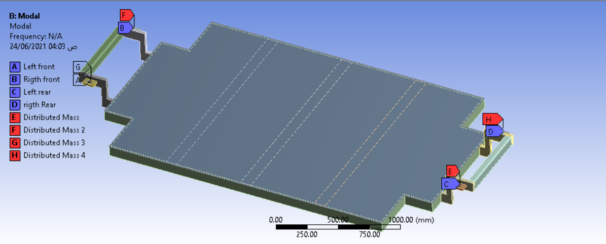 After this I should put transitional joint between the ground and the wheel , transitional joint between wheel and car body But I don't know how to put Transitional joint in Ansys Then After that I should Apply the base Excitation on the two front wheels
June 24, 2021 at 2:29 ampeteroznewman
SubscriberWhen building a simulation model, there can be more or less simplification or idealization of the real parts to make a model that predicts some response.
In the case of a car and its connection to the wheel, rear wheels are simpler than front wheels, which have to also steer the car.
In this video, you can see a simulation of the suspension links of a rear wheel. There is the hub (orange) at the center of the wheel, and there are two links (blue and yellow) from the hub to the chassis (green) of the car. Between the links are two spring-dampers(light blue/purple). This is a realistic simulation of a rear wheel suspension. In this video, the blue block at the bottom is the road and that moves up and down on a translational joint to simulation the road bump.
A highly idealized version is a Translational Joint that requires no links to be created. You have to decide what you want to put in your model. That might depend on how much time you can spend on this project. If you have time, you can do a more realistic model. If you have less time, you make a more idealized model.
June 24, 2021 at 2:39 amPaulaAmir
SubscriberI don't have too time to make realistic model , So what simplification specifically in the point of the Translational joint and the Sprung that could be done to my model to be nearly equal to the realistic model And to do idealized model that make the values Accepted And if I Want to do Base excitation on the two front wheels is there is Any boundary conditions or fixed support to the model that should be added ?
June 24, 2021 at 2:49 ampeteroznewman
SubscriberYou need a body to be the road, like the blue block in the video. That goes up and down on a Translational Joint to Ground.
You need a body to be the wheel which also goes up and down on a Translational Joint to the road Body.
You need a spring between the road body and the wheel body to have the spring rate of the tire, Ku.
You need a Translational Joint between the wheel body and the car body.
You need a spring between the wheel body and the car body to have the spring rate of the suspension, Ks and the damping Cs.
This is the most idealized version and is the 1D model that is like MATLAB. You can put a bump load into the Joint that connects the road to Ground in the form of an Acceleration-Time history or a Displacement-Time history.
Once you depart from a 1D model, the problem gets 6 times more complicated, because you have to control six degrees of freedom of each body.
This kind of model is best done in Rigid Dynamics.
June 24, 2021 at 2:57 amPaulaAmir
SubscriberIs the bodies that must be used is with the same details of the video ,As it will take too much time to do it And is their any Alternative solution for this situation.
June 24, 2021 at 3:18 ampeteroznewman
SubscriberYou can do what I described with three blocks: road, wheel, car. No time needed at all.
June 24, 2021 at 3:44 amJune 24, 2021 at 4:07 ampeteroznewman
SubscriberYes, three bodies is all you need. Make sure the wheel and car have the correct mass. Blocks are simpler than a round wheel because you have to orient the translational joints. The translational joints all need to point in the vertical direction.
It is also easier if you leave room between the road and the wheel for the tire spring and room between the wheel and the car body for the suspension spring. The springs all need to be oriented in a vertical direction.
It's late here for me so I will check back in the morning. Good night.
June 24, 2021 at 4:09 amPaulaAmir
SubscriberGood nigth And Thank you So Much DR peter For this information . I am very grateful for your help.
June 24, 2021 at 1:59 pmPaulaAmir
SubscriberGood morning Dr peter
I hope you are well
How much is the distance that must be leaved between the road and the wheel , the wheel and car body to Apply the spring In solidworks Approximately ?
June 24, 2021 at 8:58 pmpeteroznewman
SubscriberHello Paula Leave the distance of the tire height (road to rim) for the tire spring.
Leave 0.2 m between the spring attachment points on the wheel and on the car body.
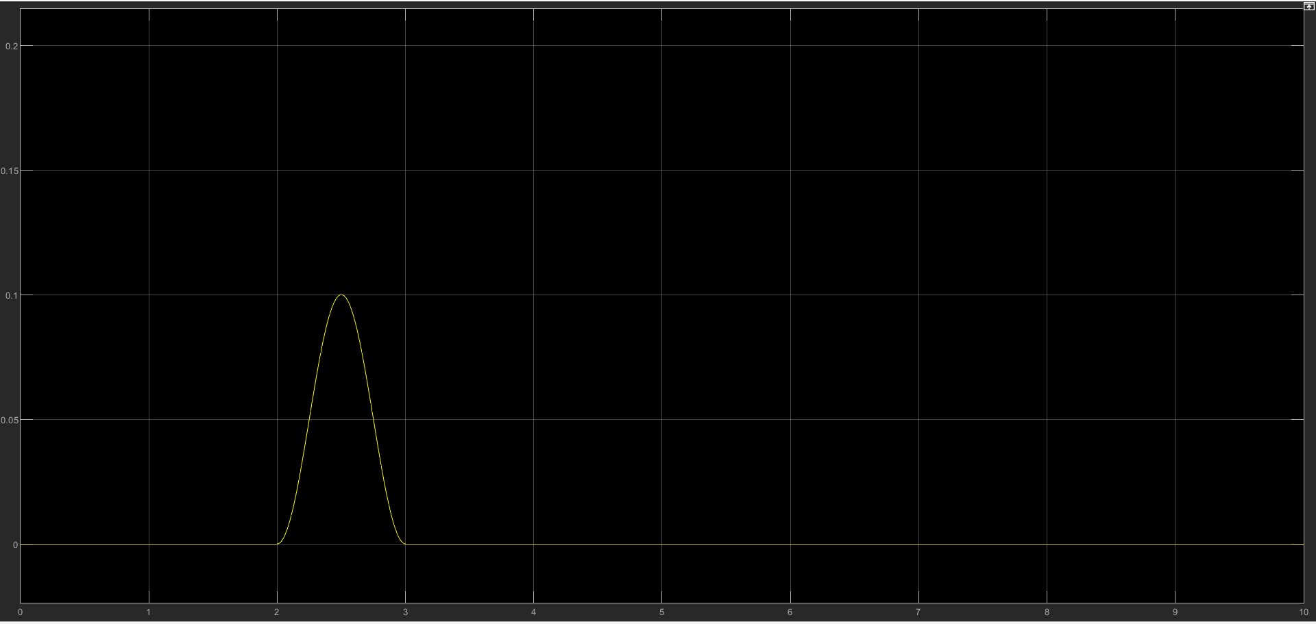
What is the input graph for the road motion?
June 24, 2021 at 10:37 pmJune 25, 2021 at 12:32 ampeteroznewman
SubscriberOkay, I see a graph with a peak of 0.1 on the Y axis at a value of 2.5 on the X axis.
What are the units on that graph for the X and Y axes?
June 25, 2021 at 12:36 amPaulaAmir
SubscriberY-Axis is M and X-Axis is sec
or by another meaning X-axis is the is the amplitude of the bump
Y-axis is the the height of the bump
June 25, 2021 at 2:53 ampeteroznewman
SubscriberOkay, you can take that input data and paste it into the Translational Joint between the road and ground as a Displacement input. That will be the Base Excitation you want. Then you can plot the displacement or acceleration of the wheel and the car body.
June 25, 2021 at 11:25 amPaulaAmir
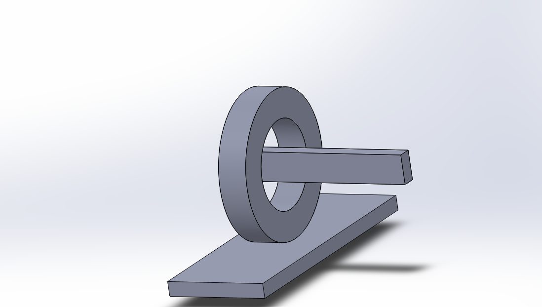
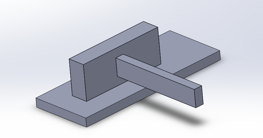
SubscriberI have left 45 mm between wheel and road ,200 mm between wheel and car body as shown in the next figure
 Then I should put these assembly In Ansys first I will have modal analysis
but what will be fixed support ? then I should take the output from modal Analysis and insert it as input to the transient Structural and insert the Acceleration and road input
June 25, 2021 at 8:34 pmpeteroznewman
SubscriberIf you use Rigid Dynamics, you don't need to use Modal Analysis first. You just import this geometry into the Geometry cell, then in the Model, create the joints and springs and import the input displacement as a joint load on the translational joint that connects the road body to ground. When you Solve, you will get a Transient solution and you can plot the displacement or acceleration of the car body and the wheel body.
You don't need a Fixed Support. The translational joint between ground and the road body, along with the input displacement load is equivalent to the fixed support.
Viewing 22 reply threads- The topic ‘Base excitation on Skateboard chassis ,large value of stresses ?’ is closed to new replies.
Innovation SpaceTrending discussionsTop Contributors-
4904
-
1598
-
1386
-
1242
-
1021
Top Rated Tags© 2026 Copyright ANSYS, Inc. All rights reserved.
Ansys does not support the usage of unauthorized Ansys software. Please visit www.ansys.com to obtain an official distribution.
-


Ansys Assistant

Welcome to Ansys Assistant!
An AI-based virtual assistant for active Ansys Academic Customers. Please login using your university issued email address.
Hey there, you are quite inquisitive! You have hit your hourly question limit. Please retry after '10' minutes. For questions, please reach out to ansyslearn@ansys.com.
RETRY
