-
-
October 16, 2023 at 11:19 am
handon
SubscriberI created a radial diffusion doping in silicon pillar by referring to the link below.
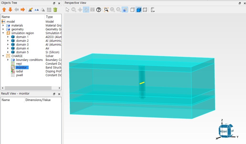
My CHARGE includes band monitor, constant background doping (n-type) and radial doping (p-type).
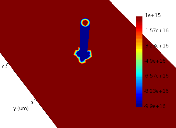
I ran the simulation and found that the radial p-n junction is formed well.
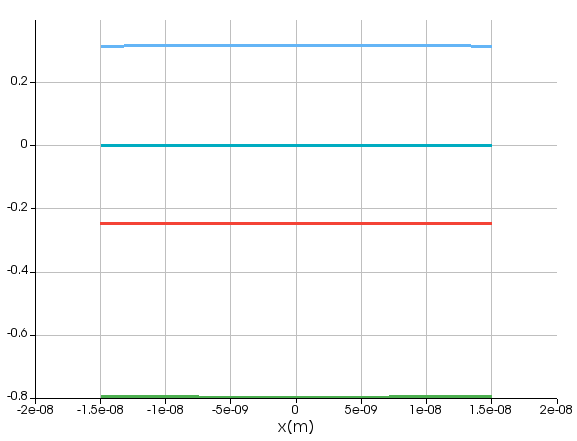
However, the band monitor showed no band bending across the pillar; it only showed a flat band structure.
Why the band bending does not occur despite the radial p-n junction being observed in doping visualization?
I have attached my .ldev file and .lsf file link so that you can check my CHARGE setting.
.ldev: https://drive.google.com/file/d/1U0_d0V2yQ3m-4_yU3GHDtUR62hdVTiUH/view?usp=sharing
.lsf: https://drive.google.com/file/d/1I9dfVqWH71awbBF6UxrsHfIKW94DT7a-/view?usp=sharing
-
October 17, 2023 at 5:57 pm
Niki Papachristou
Forum ModeratorHi Handon,
Thank you for reaching out to us. Unfortunately I am not allowed to download files from your shared drive. However, your screenshots are very helpful. For your question, I would like to ask you to check your radial geometry. From your first image it seems that there is something different to what our exmples look like. Additionally, I would like to suggest to you to make sure that the position of the monitor is at the right cross sction of the rod.
Kind Regards,
Niki
-
October 18, 2023 at 10:43 am
handon
SubscriberThanks for your reply, Niki.
Additionally, I have some questions.
In the CHARGE learning course (below link), the rectangular structure is doped by 1e+15 of n-type (base) and 1e+17 of p-type (emitter).
/courses/index.php/courses/lumerical-charge-my-first-simulation/
And the band-bending is observed clearly in the band monitor.
However, in the case of radial doping of silicon nanowire, the band is flat as I shared in the previous thread despite the doping concentration being the same in the learning course's structure. (1e+15 of n-type for base and 1e+17 of p-type for emitter)
When I set the higher doping level for each dopant type, it started to show the band bending.
Can you let me know the reason why it shows different results for structures?
Is it related to the mesh or simulation accuracy?
Also, I edited the link so that you can download the files.
Please check that you can download them.
-
October 18, 2023 at 1:32 pm
Niki Papachristou
Forum ModeratorHi Handon,
Unfortunately, I am not allowed to download files from the forum posts as it is company's policy. The differences that you are observing might be due to how you have set up your geometry and the dopants. If you increase the mesh settings I would expect to have increased accuracy on the graphs but I wouldn't expect to have the values changed.
Kind Regards,
Niki
-
- The topic ‘Bandstructure of radial diffusion doping in silicon pillar’ is closed to new replies.


-
4597
-
1495
-
1386
-
1209
-
1021

© 2025 Copyright ANSYS, Inc. All rights reserved.


