-
-
May 2, 2025 at 10:21 am
youssef.gomaa
SubscriberHi all,
I'm running a 3D static structural analysis of a ball screw assembly in ANSYS Workbench 2023 (shaft, balls, and nut). My goal is to simulate realistic mechanical coupling — i.e., when the nut rotates, the shaft should move axially in the correct direction (and vice versa).
Setup:
Frictional 4-point contact between balls and grooves (nut and shaft).
Nut = cylindrical support (allows rotation about axis).
Shaft = cylindrical support (allows axial movement only).
Asymmetric contact: balls = contact, grooves = target.
Frictional contact with small sliding off; offset ~0.022 mm; pinball ~0.2 mm.
Large deflection ON; weak springs OFF.
Time stepping: auto (20 initial, 10 min, 50 max).
Solver: direct.
Problem:
When I apply a remote axial displacement to the shaft, the nut rotates in the expected direction (e.g., shaft +X → nut −θ).
However, when I apply a rotation to the nut, the shaft moves in the same axial direction regardless of rotation direction, which is not physical. I expect reversed shaft motion for reversed nut rotation.Has anyone experienced this? Is this likely due to contact stiffness, friction behavior, or boundary condition setup? Any advice or similar cases would be greatly appreciated.
Thanks in advance!
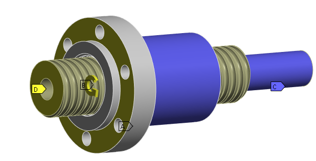
P.S.: Please ignore the remote displacement "D" in the picture. It was from another simulation.
-
May 3, 2025 at 2:13 pm
peteroznewman
SubscriberWhat output do you need from this analysis?
If all you need is an animation of the nut moving axially as the shaft rotates, you can create that with much less computational effort by deleting all the contacts and using simple joints with displacement loads.
-
May 3, 2025 at 3:14 pm
youssef.gomaa
SubscriberÂ
I need to check the stresses of the parts (balls, nut and shaft) with the given frictional contact conditions between the balls and the nut / shaft grooves. I have to make sure that the model is physically making sense, when applying torque to the nut and / or applying a rotation, where the axial movement of the shaft occurs through the transmitted axial forces from the applied torque on the nut.
Â
-
May 6, 2025 at 12:57 am
Dennis Chen
SubscriberInstead of having nuts rotating --> bolt translating, think about the problem in terms of group of nodes having one or some of the 6 DOF.Â
when you are applying a constraint, which DOF is being constrained and which is free? I don't mean what you THINK is happening, verifying it in the documentation so you are sure the solver is going to see the constraints the way you see it.    Sorry I can't give you a solution becuase I can't tell what you did 100% exactly.Â
I also think there's a matter of frame of reference. if you simply fix the shaft and rotate the nut while allowing axial displacement, the nut should translate forward (thus establishing a screw axis).  From there, with respect to the nut, the bolt is also translating and rotating.  The one you fix is your reference.Â
Also as Peter said, there's no real reason to model this directly, it's very expensive to implement in a larger model.Â
-
- You must be logged in to reply to this topic.
-
3024
-
971
-
857
-
830
-
777
© 2025 Copyright ANSYS, Inc. All rights reserved.