-
-
October 1, 2024 at 2:18 pm
ashishkumar.gupta
SubscriberHello,
I am refering to a youtube video (
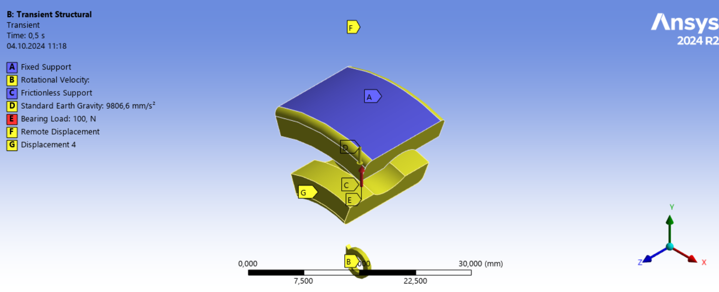
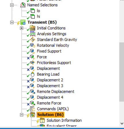
). It does not show how it does that tho.I have prepared a similar model with 9 balls, IR and OR. IR rotates (1000 rpm) and radial force also applied bcoz of shaft and OR is fixed.
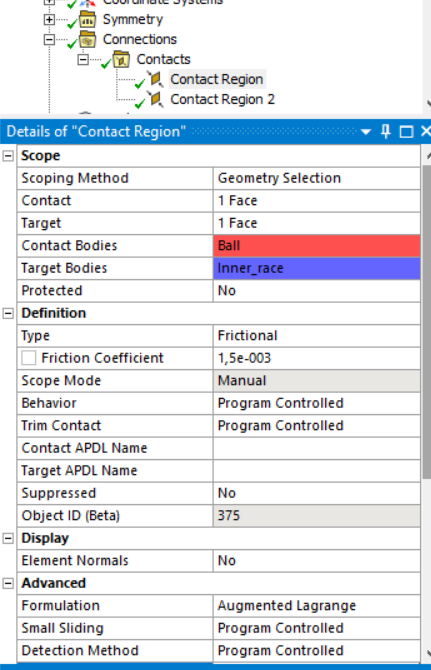
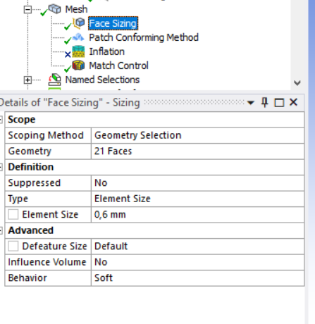
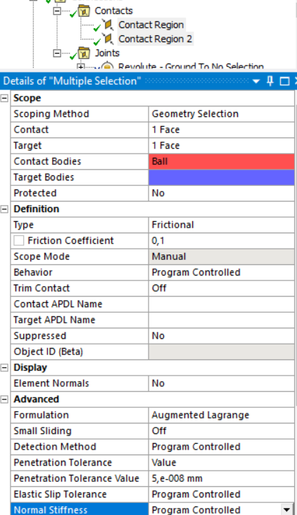
Contact is frictional (0.02; Augmentated LAgrange and Normal stiffness 0.1).
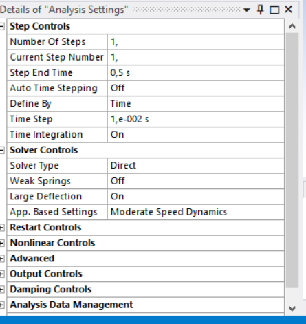
Analysis setting; End time: 10s and step size:0.1 s.
But am not getting the desired reults. Please someone help me out.!!
Thank you!
-
October 3, 2024 at 8:10 pm
ashishkumar.gupta
SubscriberHello Ansys Team, could you please help me out here?
-
October 4, 2024 at 10:15 am
Ashish Khemka
Forum ModeratorHello,
It would be difficult to comment without looking at the model. Ansys employees cannot look at the model. If you have access to Ansys support then you can raise a case otherwise please share the snapshots of geometry you have, the settings, load and boundary conditions here. It may help forum members to comment more.
Regards,
Ashish Khemka
-
October 4, 2024 at 10:22 am
-
October 4, 2024 at 10:25 am
Ashish Khemka
Forum ModeratorHello,
You can try applying the loads one by one and see if the behavior is as expected or not.
Regards,
Ashish Khemka
-
October 4, 2024 at 10:28 am
ashishkumar.gupta
SubscriberHello Ashish, I tried that way (just OR fixed and IR rotating at 1000 rpm) but it does not work. Like I cannot see the IR rotating. I do not know where am I going wrong.
-
October 4, 2024 at 10:40 am
-
October 4, 2024 at 11:01 am
-
October 4, 2024 at 11:21 am
Ashish Khemka
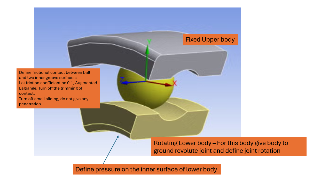
Forum ModeratorI gave a joint just to define rotation for lower body.
-
October 4, 2024 at 11:24 am
ashishkumar.gupta
SubscriberBut we can give a Rotational velocity to the IR body directly. But the thing you suggested did not simulate at all. So what should I do?
-
October 4, 2024 at 11:51 am
Ashish Khemka
Forum ModeratorTry running the model with coupling and see if it behaves as expected and then try introducing the same.
Regards,
Ashish Khemka
-
October 4, 2024 at 11:57 am
ashishkumar.gupta
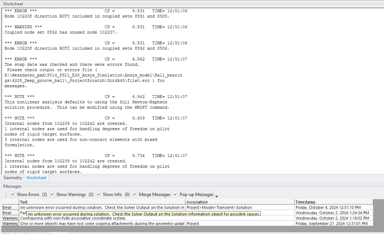
SubscriberWhat coupling you talking about? I do not understand...I tried running the model as u suggested but it gave an error, which I have already uploaded. What exactly you suggestign now?
-
October 4, 2024 at 12:09 pm
Ashish Khemka
Forum ModeratorHi,
I saw the used DOFs message in coupled set and thought that you are using CP command. It would be difficult to comment without looking into the model. Please wait for other forum members to chime in. In addition, please see if the following external link for an example on YouTube helps:
https://www.youtube.com/watch?v=ECxH7hklCJA
Regards,
Ashish Khemka
-
October 4, 2024 at 12:15 pm
ashishkumar.gupta
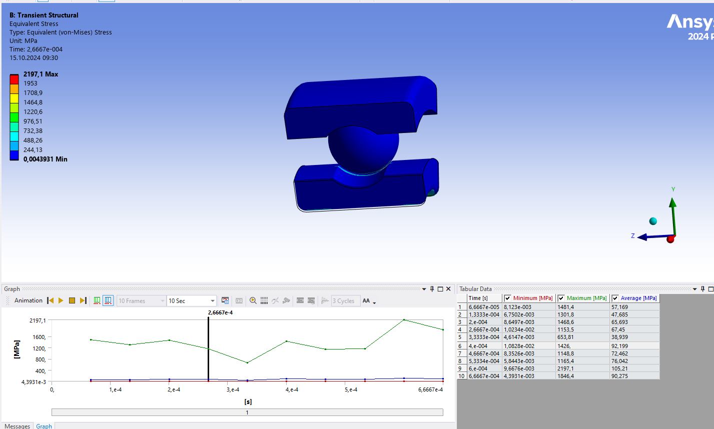
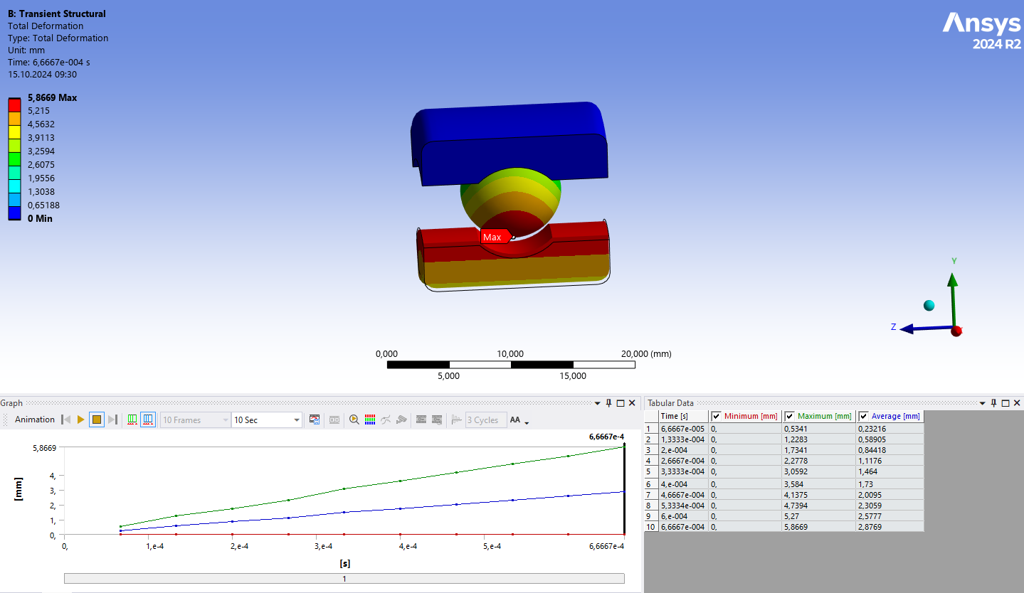
SubscriberHi, I have seen this video but that doesnt help. Plus, I have seen a post on Ansys where they suggested this video/concept does not make sense. If you look at the deformation, which is absurd.
Okay, I will wait for other ANSYS CS to help me out. Thank you !!1
-
October 7, 2024 at 6:11 am
ashishkumar.gupta
SubscriberHello Ansys Team, Any update on my issues? Your support will be highly appreciated as I have deadline to submit this project :-(
-
October 12, 2024 at 8:29 pm
ashishkumar.gupta
SubscriberHi Ashish, I am still waiting for my issue to be taken care of by the Ansys team. that was the reason of opening another post. Should I open up another post so that the team can look into it? Thank you!!
-
October 14, 2024 at 5:29 am
Ashish Khemka
Forum ModeratorHello,
My apologies for the delay in response. Ansys employees cannot download the model or provide detailded guidance on setting up the model. If you have access to Ansys Support then you can raise a case.
In addition, please see if following video is of use to you: Ball Bearing Analysis in Ansys Workbench - YouTube
Regards,
Ashish Khemka
-
October 14, 2024 at 5:53 am
ashishkumar.gupta
SubscriberThank you Ashish for missing out on the prior messages/replies. I have provided with all the necessary SS and I am not asking for the complete set-up of the model.
Alternatively, I have raised another query already and it seems, I might need to switch to another CS friendly software.
Thank you!!
-
October 14, 2024 at 2:28 pm
dlooman
Ansys EmployeeMy personal opinion is that it is impractical and of little value to analyze the actual rotation of the needle or ball bearings. Finite elements can only be rotated two or three degrees per time step. You mention an inner race rotation velocity of 1000 RPM. That 6000 degrees per second. In the video the needle bearings are rotating around 10 times faster than the race so 60,000 degrees per second. That will dictate a time step of no more than 2e-5 seconds. As the contact is constantly changing the solution will be highly non-linear. It's not impossible to do, but very time-consuming and tricky. For example, if you want to simulate the steady state condition you would need to specify initial rotational velocities for the inner race and the needles/balls. That's not possible through the gui. What result are you hoping to find about the bearings? If you are just practicing your FEA skills, try rotating a single body at 60,000 deg/sec. Even that will not be trivial.
-
October 14, 2024 at 2:39 pm
ashishkumar.gupta
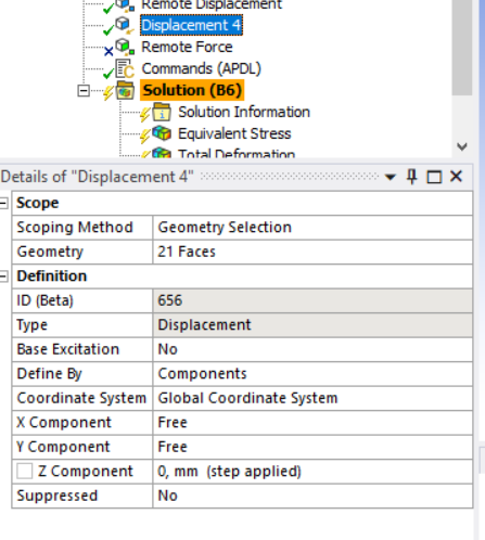
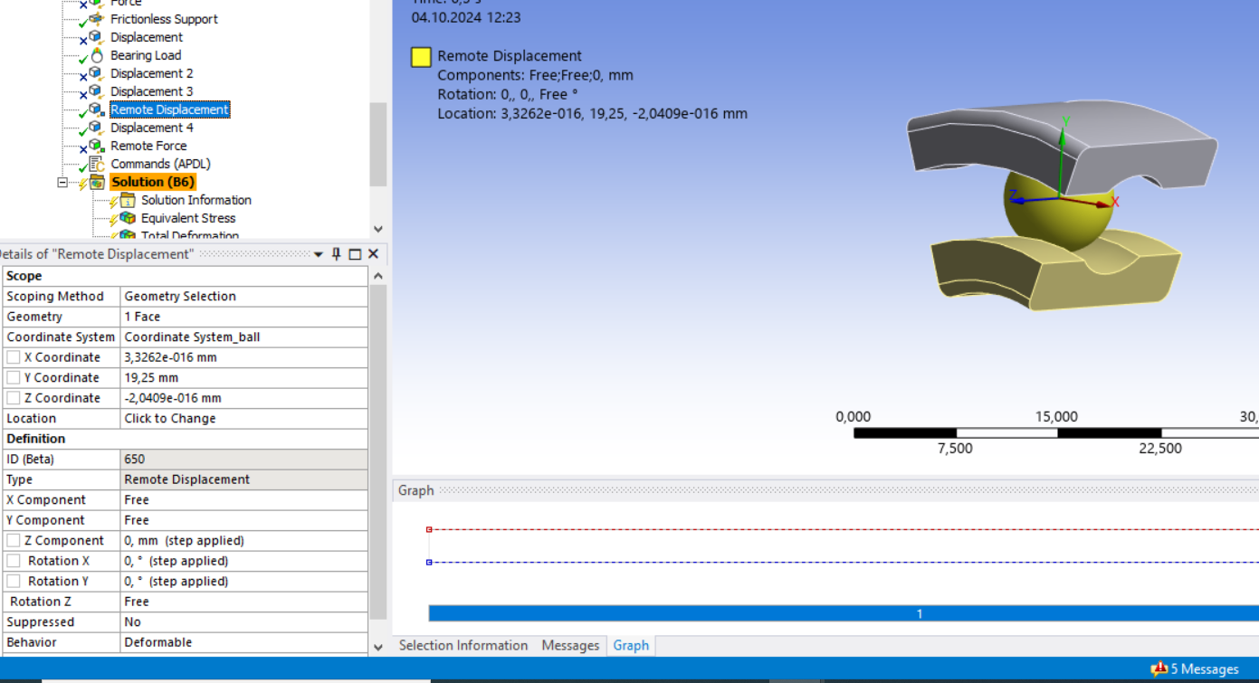
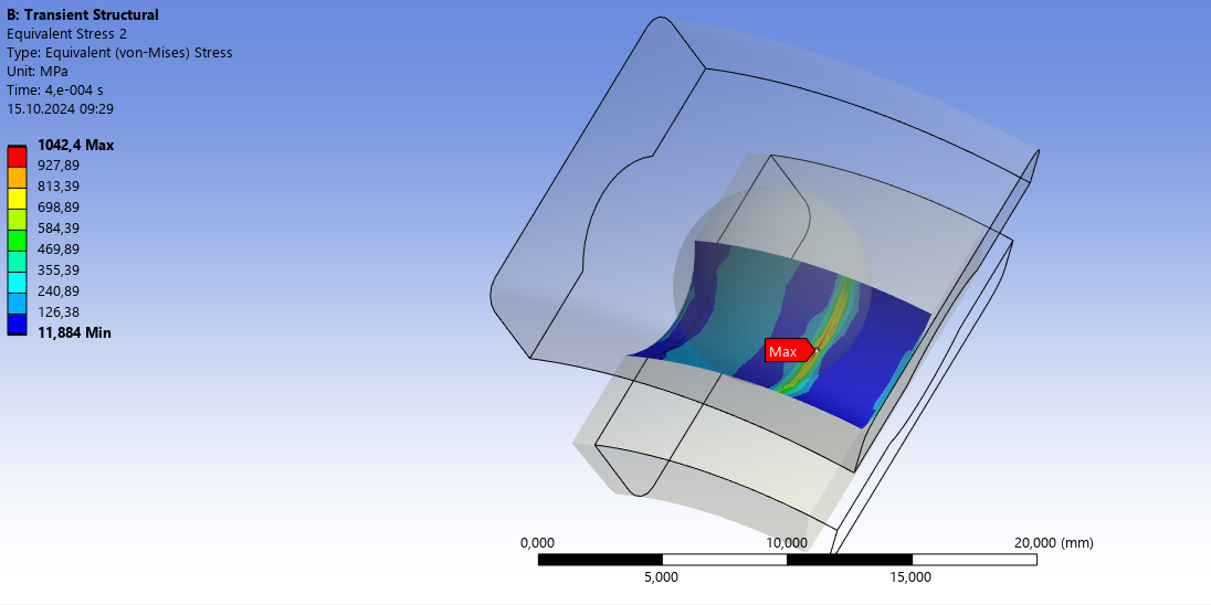
Subscriberthank you for your response. I am interested in the contact behaviour (Hertz Contact pressure) in ansys Transient. My B.C. are from 1000 RPM to 5000RPM (shaft speed = Inner Race Speed) and Outer race fixed to the housing. I have seen many videos where I see this behaviour. I am unable to find the correct B.C.
-
October 14, 2024 at 3:01 pm
dlooman
Ansys EmployeeI don't see why a transient is needed for a study of hertzian contact. The most important requirements are perfect geometry, the correct preload and a very fine mesh at the contact location.
-
October 15, 2024 at 7:31 am
ashishkumar.gupta
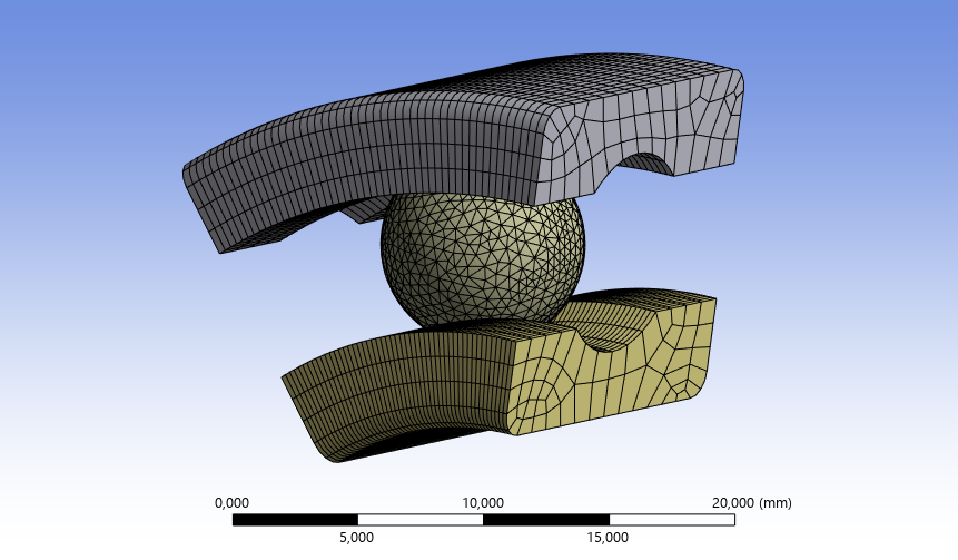
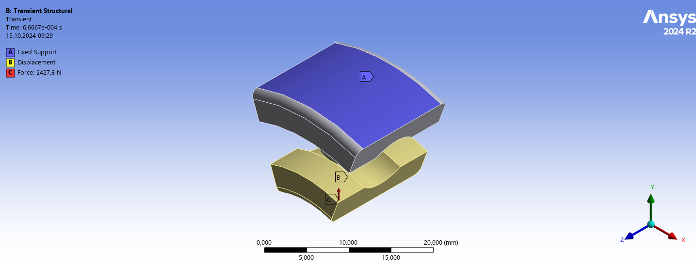
SubscriberI am making the mesh finer with time. I converted the RPM to circumferential displacement using the Global cylindrical coordinate System. the axial disp =0 and Radial is free. I am applying Radial load as this the highly loaded region/ball in the entire ball bearing. Also, the races and ball are intially touching (No Gap and No Penetration) and all bodies are flexbile and of the same material. This is what happens on the Test bench as well.
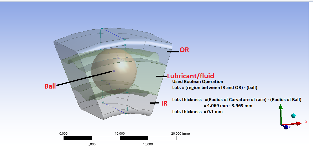
I am doing transient because I will continue this to do FSI (Mech-Fluent) and to study the EHL behaviour in the contact region.
Is there anything I should add/subtract?
Thank you!
-
October 15, 2024 at 2:19 pm
dlooman
Ansys EmployeeThen I would recommend applying a small tangential displacement to the inner race over a small time step. Or does it take some time for the CFD to reach steady state? I don't know what EHL stands for.
-
October 15, 2024 at 2:45 pm
ashishkumar.gupta
SubscriberBy Tangential, you mean cirumferential (in Y-direction in my case)...right?? EHL= Elasto-Hydrodynamic Lubrication...which means Fluid is always present between Ball and the Race ...So no metal to metal Contact....
-
October 15, 2024 at 4:07 pm
dlooman
Ansys EmployeeYes, circumferential. It's hard for me to visualize how you will introduce a thin film of fluid between the ball and the race when they are in contact in the Mechanical.
-
October 16, 2024 at 6:11 am
-
October 16, 2024 at 1:41 pm
dlooman
Ansys EmployeeYou might want to create a new post for others to consider. I have no idea how to do such an analysis.
-
- You must be logged in to reply to this topic.


-
4858
-
1587
-
1386
-
1242
-
1021

© 2026 Copyright ANSYS, Inc. All rights reserved.

