TAGGED: heat-profile, photothermal-heat-generation
-
-
October 25, 2021 at 7:54 pm
niazulkhan
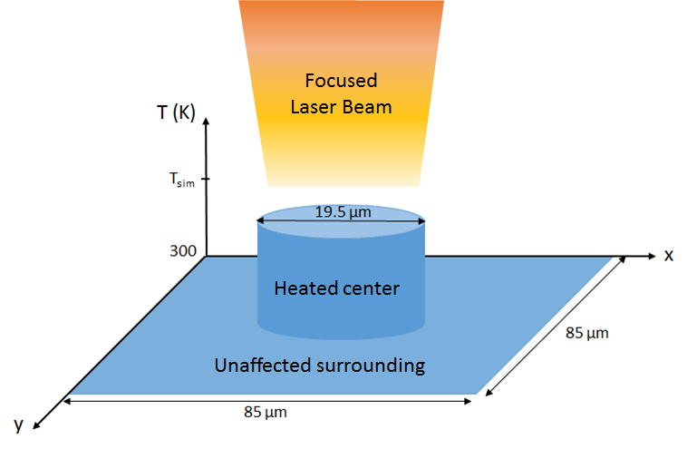
SubscriberIn the lumerical support example given here: https://support.lumerical.com/hc/en-us/articles/360041686234-Photothermal-heating-in-plasmonic-nanostructures, I am wondering how the average temperature rise was calculated using the equation: 0.0413*(Tsim - 300) where the factor 0.0413 is the ratio of the illuminated to the total area (illuminated area: 298 um2 and the total area=85 um x 85 um). I know this calculation matches with the corresponding literature. But I do not understand how the total area was taken into consideration in the FDTD or the HEAT solver. In other words, if my total area is for example 100um x 100um with the same illuminated area, how should I change my FDTD and HEAT solver?
October 26, 2021 at 3:15 pmGuilin Sun
Ansys EmployeeFor material change, it is reasonable to have temperature change since the material may have quite different thermal properties. For example if one is more conductive and the other is more resistive, the later can accumulate higher temperature.
As for the the equation 0.0413*(Tsim - 300), the online text mentions that:
By comparing the ratio of the illuminated and unilluminated area, the increment in average surface temperature is found to be equal to 0.0413*(Tsim- 300).
This means this antenna is not illuminated fully. The illuminated has 2583 antennae, so I calculated
2583*(0.34/80)^2=0.0466
However, this assumes top-hat illumination but the actual illumination is a Gaussian beam. Thus at the edge of the 2583 antennae the actual temperature is lower. You could use such Gaussian beam to weight the temperature. I hope this helps.
November 1, 2021 at 1:56 amniazulkhan
SubscriberThanks a lot, I understand how it was calculated= (illuminated area/total area)* (Tsim-300).
Total area was used as 85 um x 85 um, but I do not understand how this total area affects the simulation parameters in FDTD . If for example, the total area is 100 um x 100um, what change I will make in the FDTD or HEAT solver?
November 1, 2021 at 4:39 pmGuilin Sun
Ansys EmployeeThe total area does not change the simulation result, but only the coefficient.
November 1, 2021 at 5:00 pmniazulkhan
SubscriberI understand that. But then the average temperature will not match the theoretical values calculated by the equation: q=s*k* (temperature rise) mentioned in the paper below. The equation is for semi-infintie heat disk (which is true for 100um x 100um also) and not a function of the total area.
[1]Z. J. Coppens, W. Li, D. G. Walker, and J. G. Valentine, "Probing and Controlling Photothermal Heat Generation in Plasmonic Nanostructures," Nano Letters, vol. 13, pp. 1023-28, 2013.
November 1, 2021 at 5:29 pmGuilin Sun
Ansys EmployeeDuplicating other's result can be challenge, please refer this post: Ansys Insight: Why my simulation result is different from published paper or experiment?
Viewing 5 reply threads- The topic ‘Average temperature rise calculation in Diabolo antenna plasmonic heat generation’ is closed to new replies.
Innovation SpaceTrending discussionsTop Contributors-
4823
-
1587
-
1386
-
1242
-
1021
Top Rated Tags© 2026 Copyright ANSYS, Inc. All rights reserved.
Ansys does not support the usage of unauthorized Ansys software. Please visit www.ansys.com to obtain an official distribution.
-


