-
-
November 20, 2024 at 8:35 am
kubatycjan
SubscriberHello all,
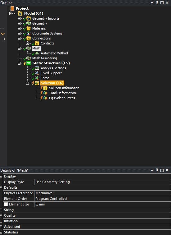
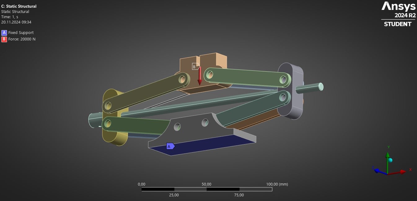
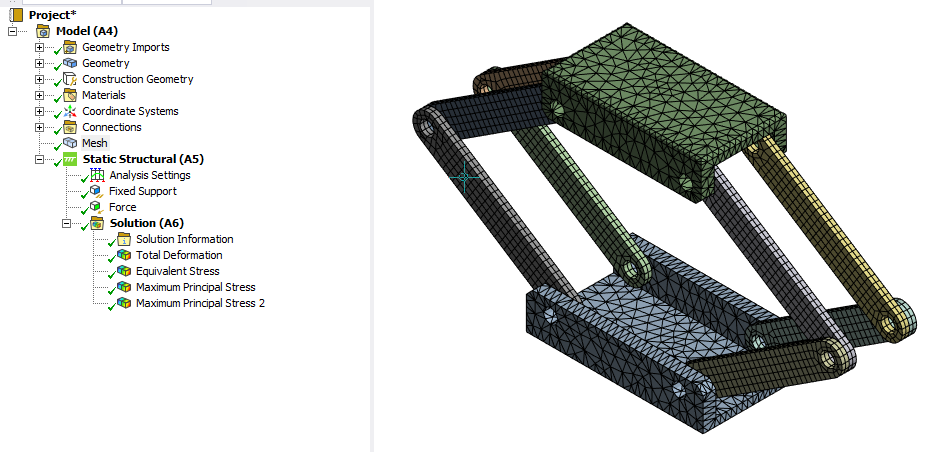
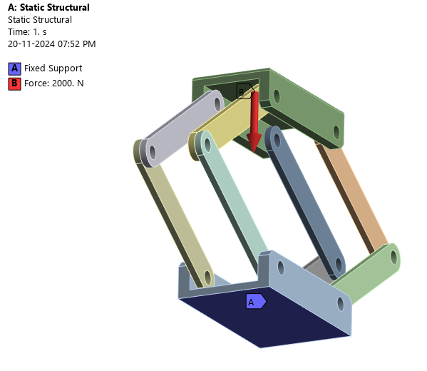
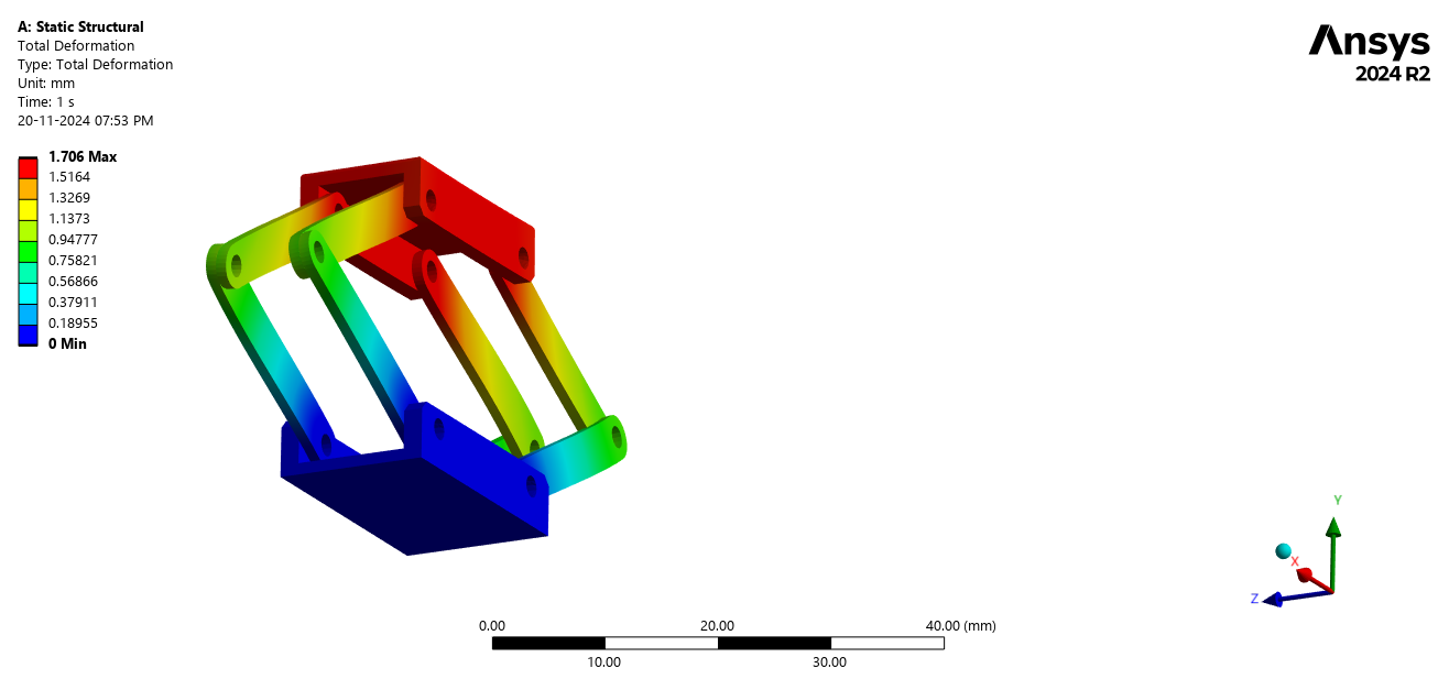
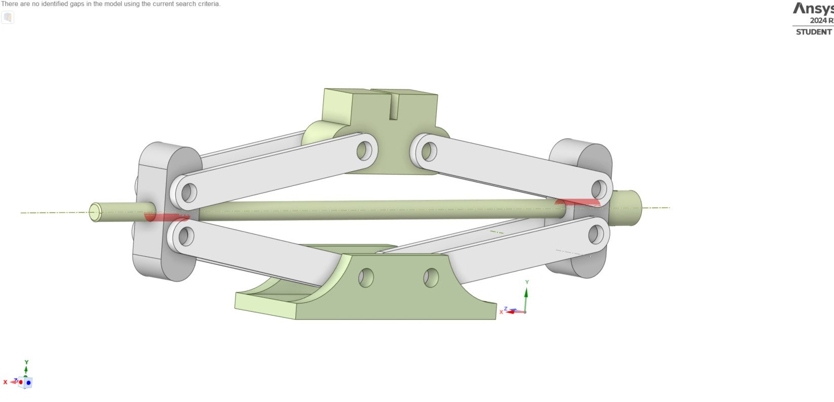
I am trying to do the ANSYS static structural simulation on my assembly component; self-made car jack.
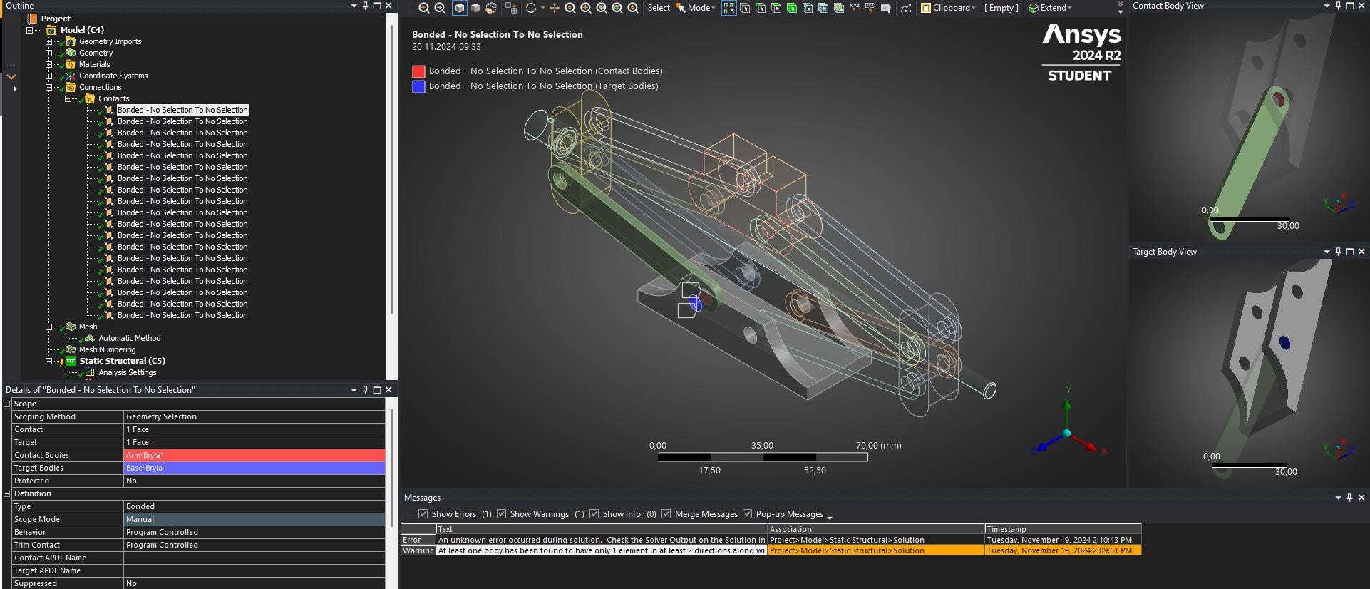
Beetween elements of my tool I used in contacts Bonded. What's more Ansys seems to see the connections beetween components even though I indicated them. I have used mesh size = 5mm and mesh numbering to reduce number of nodes.
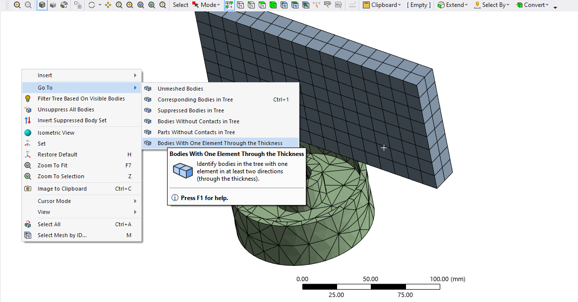
During an analysis this warning showed up: At least one body has been found to have only 1 element in at least 2 directions along with reduced integration. This situation can lead to invalid results or solver pivot errors. Consider changing to full integration element control or meshing with more elements. Offending bodies can be identified by Right-clicking in the Geometry window and choose Go To -> Bodies With One Element Through the Thickness. Refer to Troubleshooting in the Help System for more details.
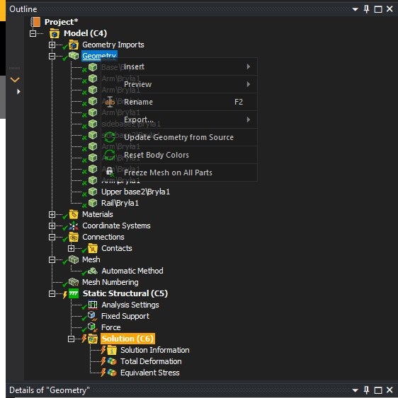
Error: An unknown error occurred during solution. Check the Solver Output on the Solution Information object for possible causes.Does anybody know solve this problem ? Cause I don't have any idea how to find this Go To -> Bodies With One Element Through the Thickness. Or maybe the elements of the car jack are to big and I need to minimize them.
-
November 20, 2024 at 10:02 am
Erik Kostson
Ansys EmployeeHi
This post shows how to see/get which body it is reporting in the warning/error msg.
https://innovationspace.ansys.com/forum/forums/topic/harmonic-acoustic-analysis-2/
Alsos one can just follow the advice:
Offending bodies can be identified by Right-clicking (on your mouse) in the Geometry window and choose Go To -> Bodies With One Element Through the ThicknessAll the best
Erik
-
November 20, 2024 at 10:30 am
kubatycjan
Subscriber-
November 20, 2024 at 10:36 am
-
November 20, 2024 at 10:36 am
Erik Kostson
Ansys EmployeeClick on the Geometry Window not the Geometry Tree (Geometry Window is where the mesh and results say are shown)
-
November 20, 2024 at 11:11 am
kubatycjan
SubscriberAlright, I think , I found the source of my problem. Then what is suppose to with those arms ? Should I change size elements in mesh or their geometry ?
-
November 20, 2024 at 11:15 am
-
November 20, 2024 at 11:31 am
kubatycjan
SubscriberThank you, by the way do You know how to change full integration element control ?
-
November 20, 2024 at 11:36 am
Deepak
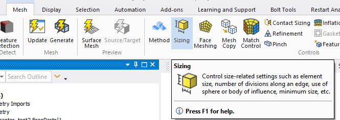
Ansys EmployeeYou can find a video on YouTube with the title "Enable Full Integration Element Control in Ansys Mechanical", which shows how to change the element control.
-
November 20, 2024 at 12:02 pm
kubatycjan
Subscriber -
November 20, 2024 at 12:11 pm
Deepak
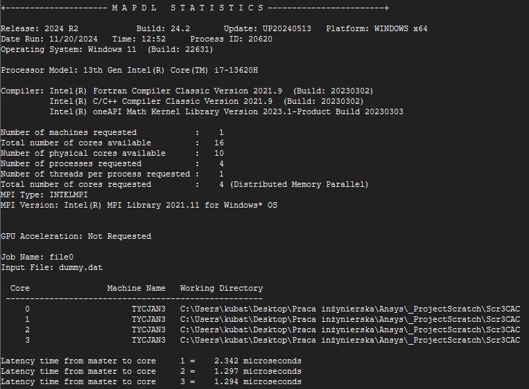
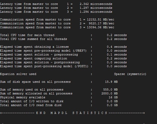
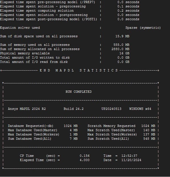
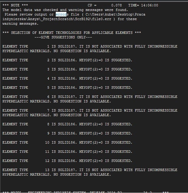
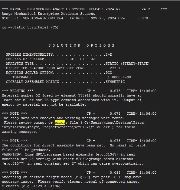
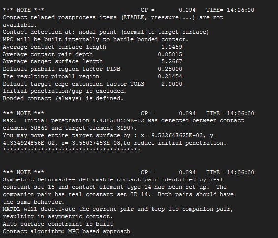
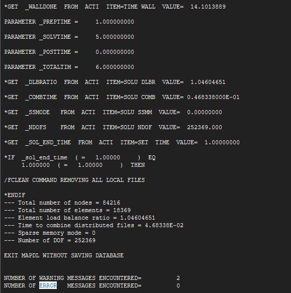
Ansys EmployeeI didn't find any error message in those snips, can u please find the "ERROR" word in the file and share that message?
Can you please try with the default mesh size, and what was the arm thickness?
Please verify that all the bodies are constrained properly.
-
November 20, 2024 at 12:54 pm
-
November 20, 2024 at 1:01 pm
Deepak
Ansys EmployeeSet the element size of the arms to 1.2mm, and Rest all to default.
For the contacts, select all contacts and right click > select "Renaming Results Based on Definition"
-
November 20, 2024 at 1:15 pm
-
November 20, 2024 at 1:19 pm
Deepak
Ansys EmployeeAre you able to solve it? The above snips show a "0" Error.
-
November 20, 2024 at 1:36 pm
kubatycjan
SubscriberNo, I can't. The analysis was finished in the bar below it was showed 99%, but then the error suddenly emerge
By the way can you please how to verify that all the bodies are constrained properly ?
-
November 20, 2024 at 2:24 pm
-
November 20, 2024 at 3:17 pm
-
November 20, 2024 at 4:07 pm
Deepak
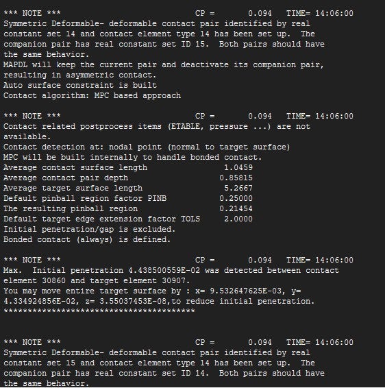
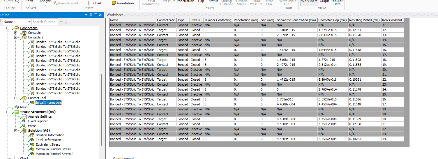
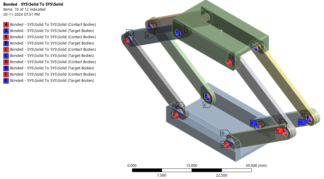
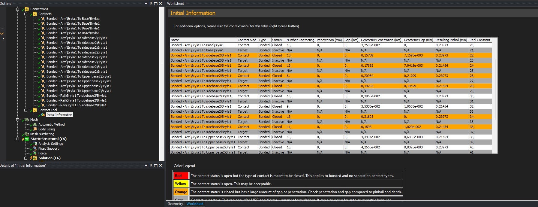
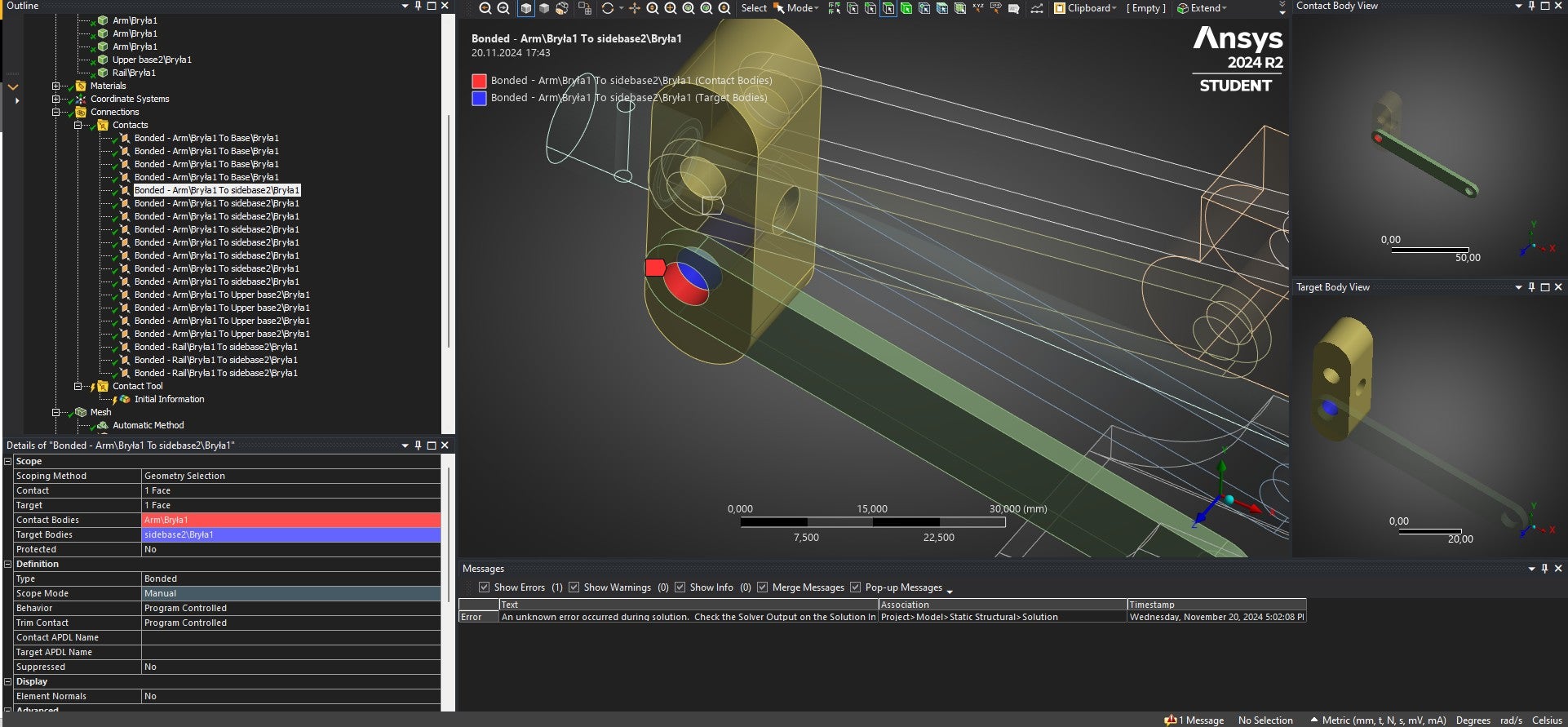
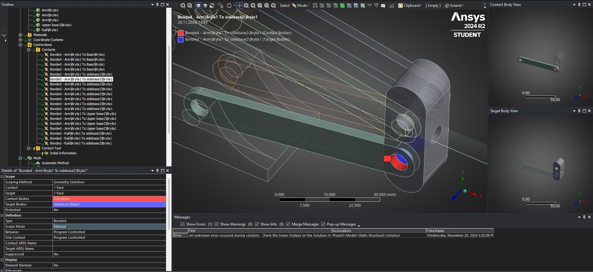
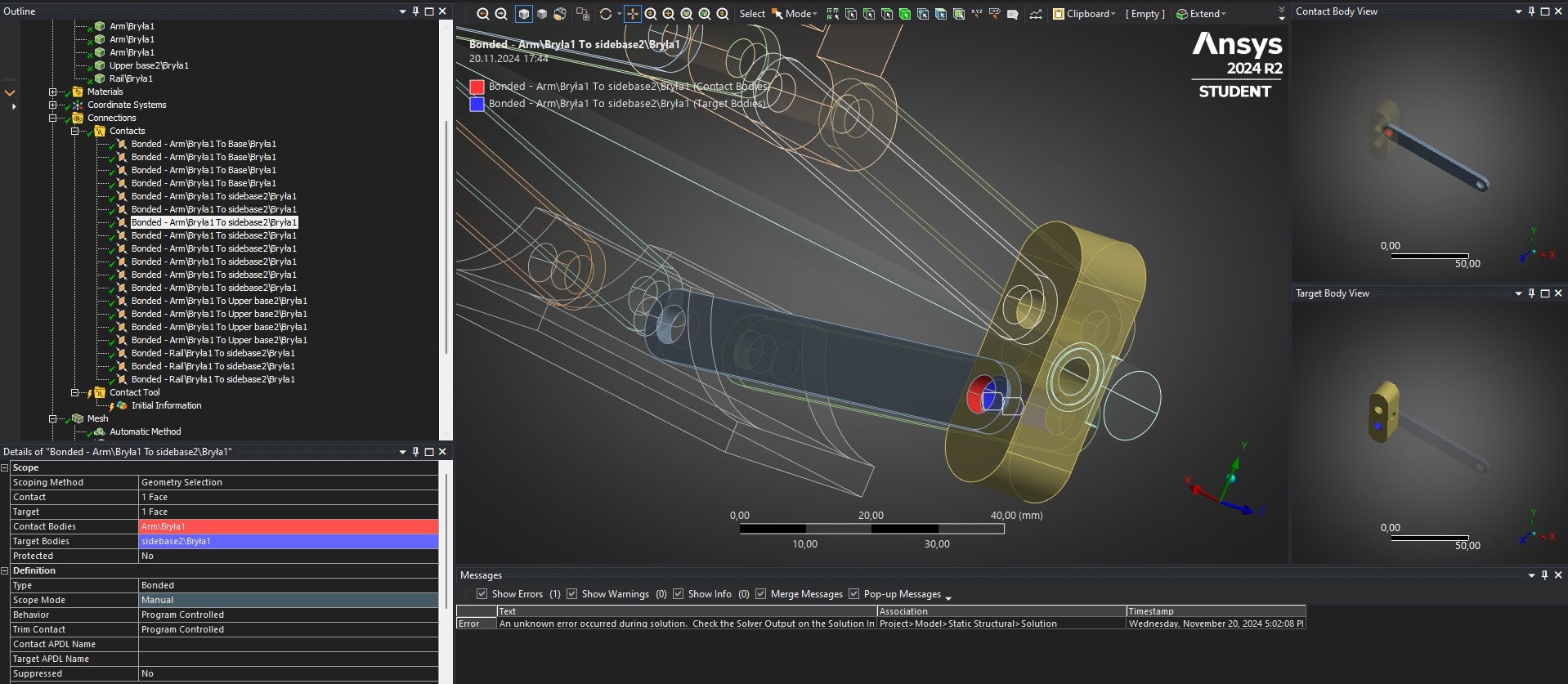
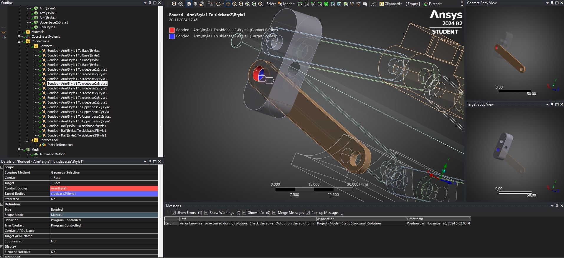
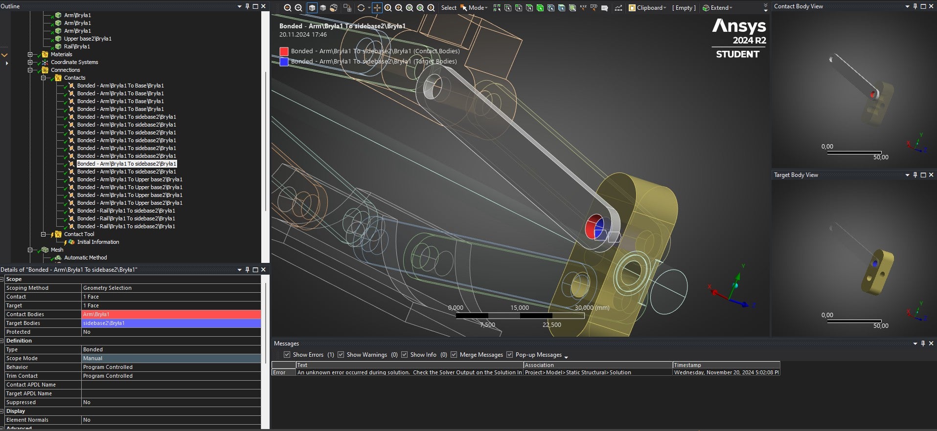
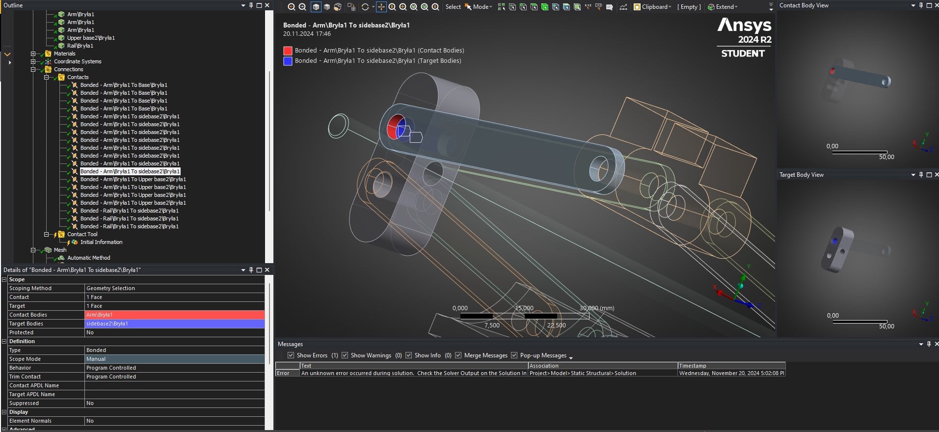
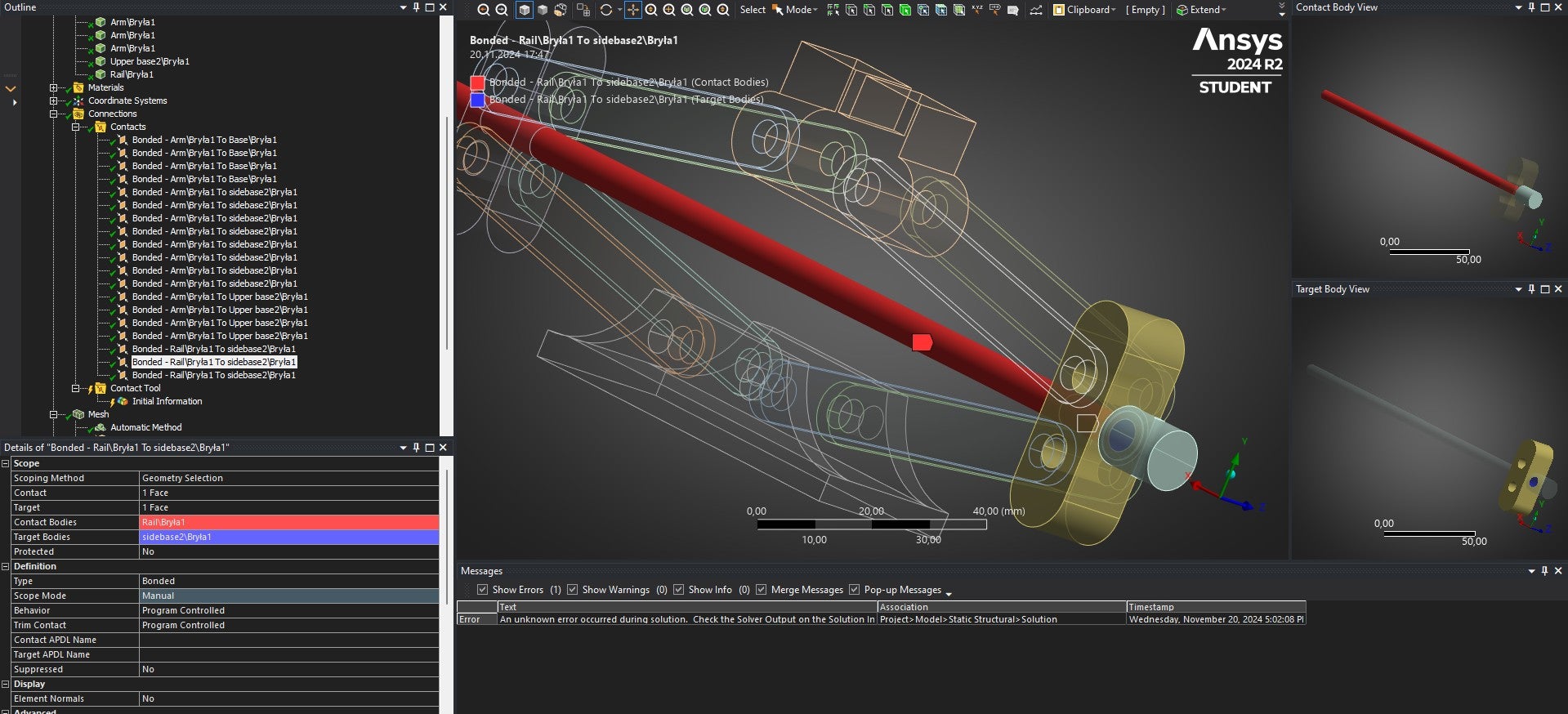
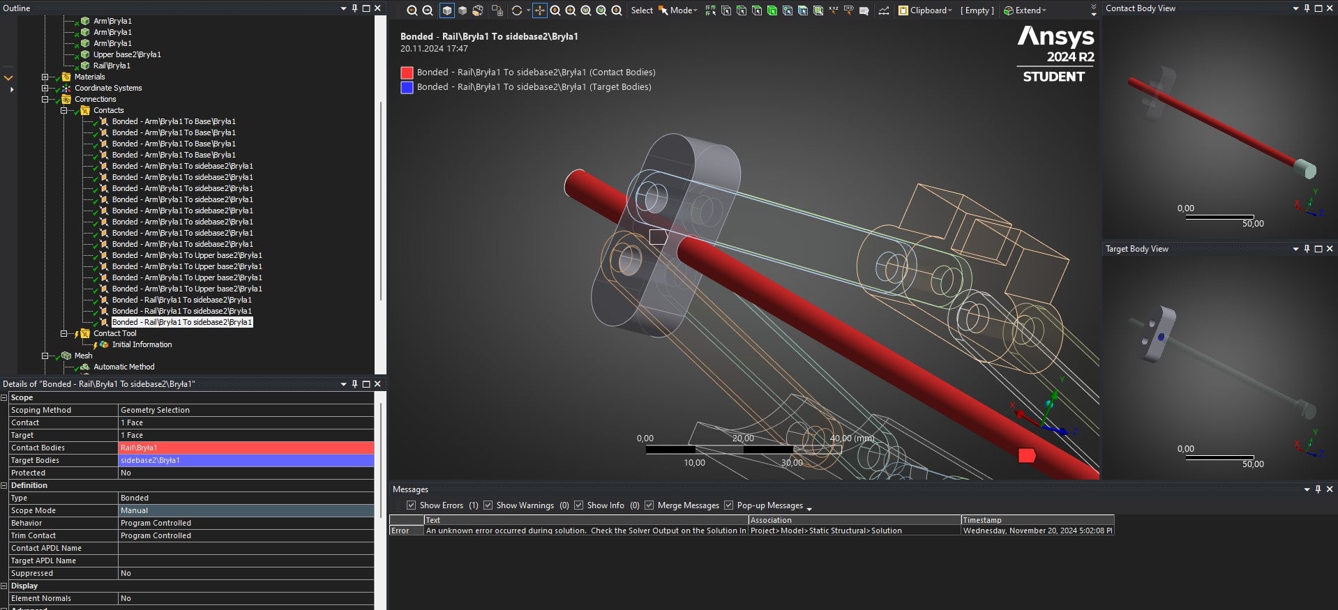
Ansys EmployeePlease check the contacts that are in orange legend, and pre-clean the geometry without penetration. Please share the snip of one of those contacts.
-
November 20, 2024 at 4:23 pm
kubatycjan
Subscriber"Share the snip of those contacts" ? You mean by changing their contact bodies ? Instead of holes in the arms and side basses , choose their faces or edges where they have contact ?
-
November 20, 2024 at 4:30 pm
Deepak
Ansys EmployeeNo, the contacts that are in orange in "initial information of contact tool", share those contact images. I was trying to see for which contact pair it is giving the penetration.
-
November 20, 2024 at 4:52 pm
-
November 20, 2024 at 5:02 pm
Deepak
Ansys EmployeeHelp check the clearance and any interference in the design of sidebase1 and sidebase2.
-
November 20, 2024 at 5:41 pm
-
November 20, 2024 at 5:58 pm
kubatycjan
SubscriberIs there any posibility to send you this file so You can check on it ?
-
November 21, 2024 at 7:16 am
Deepak
Ansys EmployeeSorry, sharing the file in the forum is not allowed. You can try to running the simulation by suppressing the screw part.
-
November 21, 2024 at 10:22 am
kubatycjan
SubscriberThank You, but I need this rail in Engineering Thesis. If my upper basis are the source of the problem the best option would be toa check out Model in Spaceclaim and again assemble them with arms ? Or do You have other idea ?
Best Regards
-
November 21, 2024 at 11:28 am
Deepak
Ansys EmployeeYes, that was a good option to clean up geometry in spaceclaim and assembly the parts properly.
-
November 21, 2024 at 11:52 am
Deepak
Ansys EmployeeYou can also try defining the revolute joints b/w arms.
-
-
-
November 20, 2024 at 10:11 am
Deepak
Ansys EmployeeHi,
Please look into this forum discussion solver-pivot-error-1-element-in-at-least-2-directions-errorThanks,
Deepak
-
- You must be logged in to reply to this topic.


-
1081
-
447
-
390
-
225
-
201

© 2024 Copyright ANSYS, Inc. All rights reserved.

