TAGGED: stress-singularity, unrealistic-stress
-
-
December 17, 2024 at 7:24 ammaximusSubscriber
Hello,
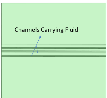
div>I am working on a Thermo-structural analysis of a printed circuit heat exchanger (PCHE, it is a 50 stack HEx) model where I need to determine the appropriate thickness of the top plate. For simplification I'm just considering the top plate and the plate below it. The key loading conditions are:
Maximum temperature: 535°C(both the bodies)
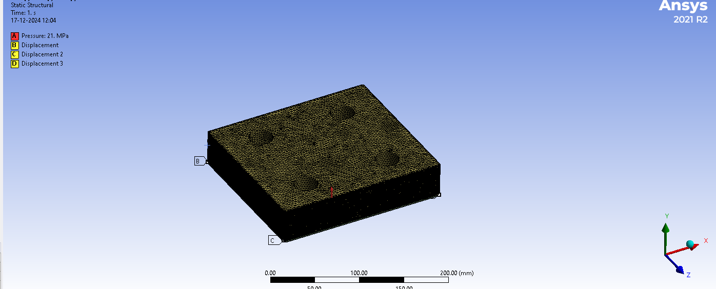
Pressure acting on the top plate(due to the fluid in the channels of the immediate below plate): 210 barTo determine the stresses, I have attempted several boundary conditions:Fixing the side surfacesFixing the bottom surface (I understand this may be over-constraining the model)Using remote displacementAdding extensions to the side surfaces and fixing themUnfortunately, none of these approaches produced satisfactory results.
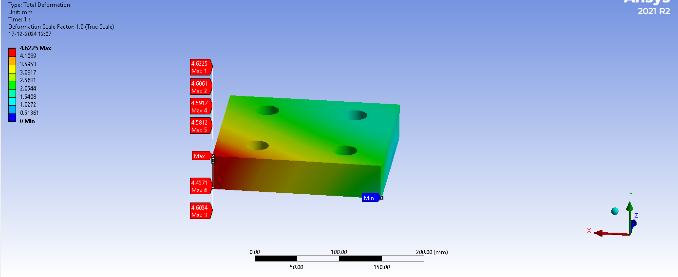
As a final attempt, I applied the 321 rule to constrain the model, allowing it to freely expand. While this approach resulted in zero thermal stress(which seems promising), I observed the following:
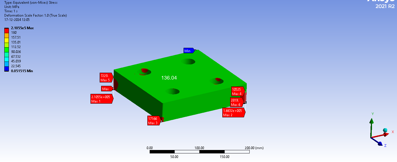
Under pressure, the stress in most parts of the plate is below the yield point.However, stress concentrations remain very high at the fixed points and their surroundings.At this point, I am unsure if my current approach is correct or if there is a better way to define the boundary conditions to obtain realistic results. So my queries are as follows:1)What type of restraining boundary condition is suitable for the analysis?2)Is 3-2-1 principle the right approach?3)Even when the 3-2-1 principle(if this is the correct approach) is used, it’s resulting in very high stresses at the fixed points. So what should be done to eliminate them?I am attaching few pictures of the geometry profile and the results obtained when the 3-2-1 rule was employed.Could someone kindly provide insights on the correct boundary conditions for this type of simulation? Your guidance would be invaluable in resolving this issue.Edit: the deformation and stress values are increasing with mesh refinement(even though the mesh is fine).
-
There are three sources of high stress at fixed supports. Poisson effect, constrained thermal expansion, singularity of a point support. With the 3-2-1 method you have eliminated the first two sources, but you still have high stress due to supporting the model at a point, which in the limit of mesh refinement has no area. You could just ignore this stress or you could create a small area to scope the support to. If you use deformable behavior the fixed support won't produce high stress due to the first two sources. Or you could use a soft elastic support to support the model in y and then 2-1 lateral displacements to support the model in x and z.
Thanks for the quick reply. I had applied remote displacements (with the behavior set to deformable) individually for each of the four sides of the top plate, but I felt it wasn't the right boundary condition because the stresses were very high throughout the entire body. Regarding the elastic support, I applied it to the bottom of the model by assigning a large value to the foundation stiffness (since it was throwing an error about exceeding the internal solution magnitude limit for smaller values), but in this case, the stresses were very low.
You shouldn't need a large value for the elastic foundation stiffness, but it only provides a constraint perpendicular to the surface. You still need lateral constraints. That's probably why you got the error about internal solution magnitude limit exceeded.
But what boundary conditions should I apply to constrain it laterally? Whichever condition I use to constrain it laterally - such as displacement, remote displacement, or fixed support - always results in unrealistic stresses. Basically, whenever I use a condition that restricts the model from expanding (which is obviously the case), it leads to high stresses. This is why I resorted to the 3-2-1 rule.(But even this has unrealistic stresses at the fixed points)Â So are there any other boundary conditions which doesn't result in high stresses?
You can constrain UX and UZ at one vertex and UZ at a vertex offset from the first one in the X direction. These are "kinematic" constraints which don't prevent thermal expansion. Â
I tried this, but the stresses turned out to be very low (the maximum stress was only 29 MPa). Also, there was a warning about not preventing rigid body motion. The boundary conditions I used were restricting UX and UZ, and an elastic support for Y.
The elastic support would tend to cancel out the pressure load. Is the pressure load supposed to be carried at the bolt holes? If so, a remote displacement in UY could be used at the center of each hole instead of the elastic support. Use deformable behavior to prevent non-physical thermal stress. (The warning message can be ignored. The program isn't considering the role of the elastic support to prevent rigid body motion.)
In reality, the holes are primarily used to accommodate the pipes that carry the fluids. The heat exchanger is fixed in such a way that hemispherical headers are welded to it on all four sides. Additional plates are then welded to the headers and bolted in place. I attempted to replicate this fixture setup,but it resulted in high stresses(think it's overconstrained). I don't quite understand how it works in reality(because that is how the one which is in use is fixed)but not in the simulation. In any case, I tried using remote displacement at the center of each hole, but the progress bar gets stuck at 40%.
If the holes aren't the support points perhaps you can support the model at the sides, but using deformable behavior. The model looks very thick compared to its lateral dimensions. It would take a tremendous pressure to produce a non-negligible stress.Â
Â
I had tried that(remote displacement to 4 sides using deformable) earlier as well, but again the stresses were way above yield point. After experimenting all those itself I resorted to 3-2-1 rule. And I did not understand the last line.
Â
Last line was just my impression that the geometry didn't look like something real.  Too thick.  That's just my impression though.
I meant the tremendous pressure part. Also the objective of the simulation is to determine that minimum thickness of the top plate. So are there any other approaches which doesnt yield unrealistic stresses or my approach of 3-2-1 rule the most appropriate one?
- You must be logged in to reply to this topic.
- Error when opening saved Workbench project
- At least one body has been found to have only 1 element in at least 2 directions
- Script Error Code:800a000d
- Elastic limit load, Elastic-plastic limit load
- Element has excessive thickness change, distortion, is turning inside out
- Image to file in Mechanical is bugged and does not show text
-
1882
-
802
-
599
-
591
-
366
© 2025 Copyright ANSYS, Inc. All rights reserved.