TAGGED: fracture-mechanics
-
-
October 13, 2023 at 1:21 pm
Benedikt Huber
SubscriberHello, I have a question regarding the fracture Mechanics tool of mechanical:
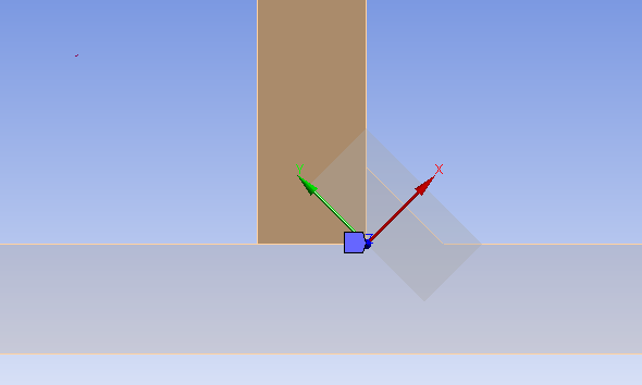
I want to calculate the Stress Intensity Factors for a semielliptical Crack starting at the weld root. (Crack starts at weld root, goes to x-direction with 45 ° in the next picture)
Because of geometric boundary conditions, the "Semi-Elliptical Crack" can't be meshed. So i defined an "Arbitrary Crack" with a semi elliptical surface body and put it at the weld root. The brown plate (picture above) is only connected to the fillet weld and not to the plate beneath.
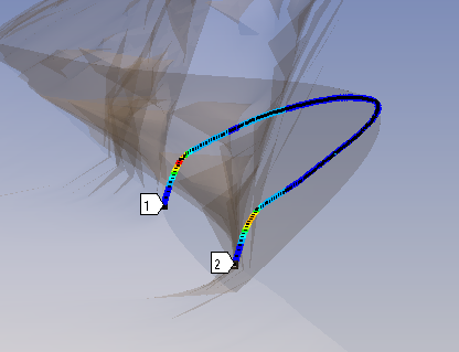
Even though results are calculated, they don't seem to be right. Also the crack front seems to be "buckled".
Is ist because the Crack starts at an edge ?
How can you calculate correct SIF in this case ?
-
October 17, 2023 at 4:19 pm
David Weed
Ansys EmployeeHi,
An arbitrary crack should work in the case of an edge crack (a premeshed crack will work as well). The x-axis for your local crack cs is pointed in the opposite direction of crack growth; you should flip this around. Also, for the buckling shown along the path of the SIF plot, what does the overall deformation in that area look like? If the brown plate is only connected to the filet (which I assume is a small area because I can't see it clearly on the picture) then might the brown plate be allowed to rotate relative to the bottom plate (as well as penetrate it)? Is the arbitrary crack only in the fillet? Maybe you can show how the mesh looks and the Arbitrary crack object settings?
-
October 18, 2023 at 8:42 am
Benedikt Huber
SubscriberHi,
thanks for your reply.
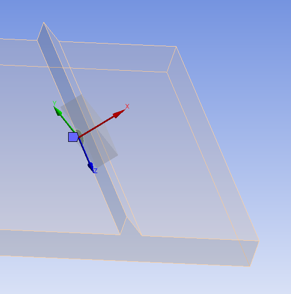
So the crack is in the fillet weld, and in this case, i think the x-axis is pointed in the right direction. In this picture you see the situation from another angle, and without the top plate.
There is only a “bonded contact” between the fillet weld and the “brown” plate.
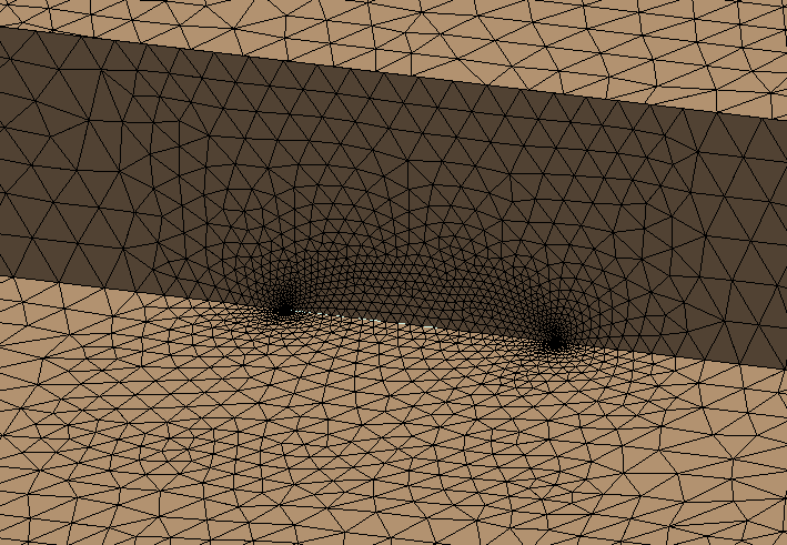
The mesh size for all bodies is 2.5 mm, and looks like this:
and the mesh of the crack looks like this (without plate):
The parameters of the crack are:
Growth factor: 1,2
Element size at crack front: 0,1mm
with 6 contours.
The deformation of the system looks like this. The blue arrow is the applied Load, and i marked the crack red.
In the following picture, you can see a section plane through the crack with the von mises stress distribution. One thing i observed was, that even though i defined a bounded contact between the plate and the fillet weld, it seems like there is a gap between those two bodies at some parts. How can that be ?
-
October 18, 2023 at 7:30 pm
David Weed
Ansys EmployeeThanks, I can now see that the x-axis is oriented correctly. I don't see a gap between the plate and fillet weld in the picture shown. If you post-process the contact status does it indicate that there is a measurable gap? You may alternatively consider using shared topology to join the two parts. Note that if contact elements are within the vicinity of the crack area, this could negatively impact the fracture parameter calculations. Using shared topology eliminates the need for contact elements and also gives a conformal mesh across the boundaries of the two bodies.
-
November 2, 2023 at 11:04 am
Benedikt Huber
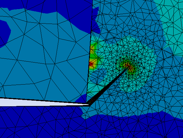
SubscriberThanks, I now have modelled the whole thing as one body with one consistent mesh. implemented a gap between the two Plates of 0.5mm Thickness. I meshed the edges of the notch with an element size of 0,2mm and the whole body with 2mm.The crack now starts at the top corner of the notch (red line in the picture).
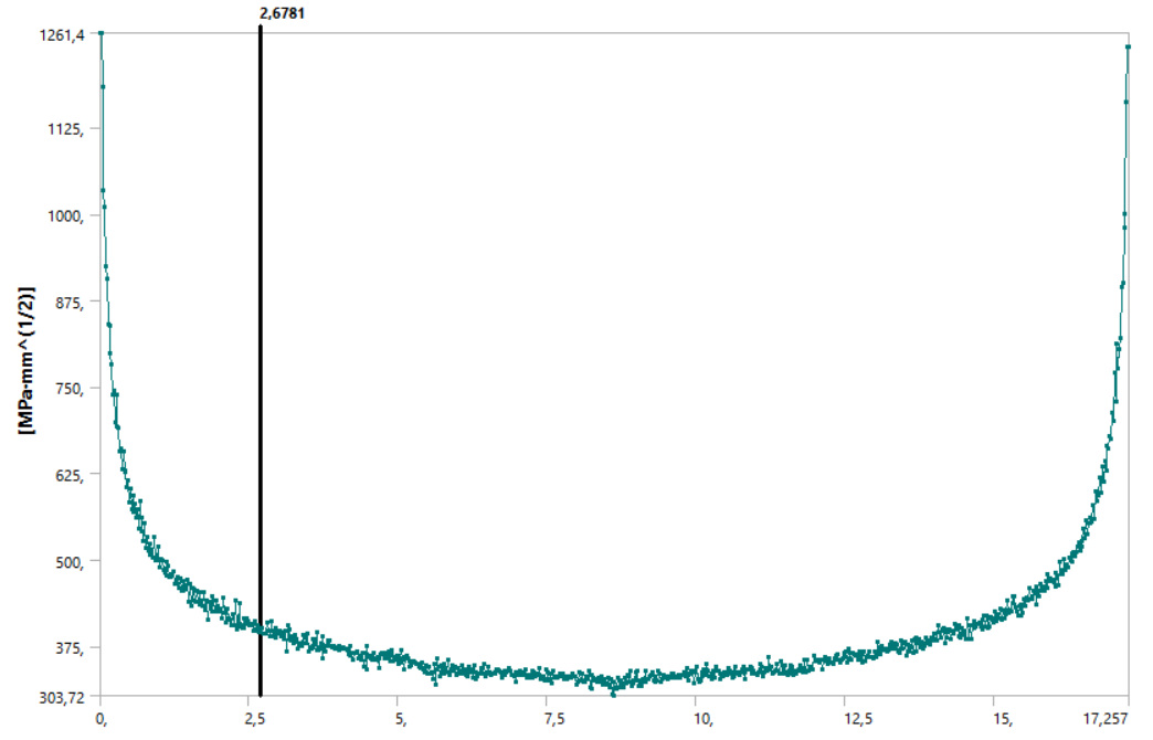
The crack now seems to be straight and not buckled. However, the value of the KI at the corner seems to be singular and depends on the element size of the crack front. In the next picture you can see the results for KI for elementsize of the crack front ranging from 0,25 to 0,025mm.
So, how can i choose the correct elementsize of the Crack front ? And can the SIF be calculated correctly at all if the crack starts at an edge, thus at a notch ?
-
November 2, 2023 at 3:39 pm
David Weed
Ansys EmployeeIf your initial crack length is 'a', can you try an element sizing of a/10 and a/20 to see if the SIF values are relatively close? Also, the SIF values for contours 3-6 should converge and will be more accurate than contours 1 and 2, which are typically the least accurate due to being closes to the stress singularity. Lastly, are your material properties linear elastic?
-
November 2, 2023 at 4:51 pm
Benedikt Huber
SubscriberMy Material Properties are linear elastic.
In my example, i have an initial crack size of 3mm. With an element sizing of a/10 (0,3mm)-> K1=713,3; Contour 6. With a sizing of a/20 (in my case a/15; 0,2mm) -> K1=814,37; Contour 6.
Also, when the elementsize at the crack front is smaller than around a/70 the contourlines aren't straight lines, but rather Wavelike, because the each Points are far away from eachother. Sort of looking like this:
-
November 6, 2023 at 9:36 pm
David Weed
Ansys EmployeeAre there any other loads/BC's in the model besides the initial load that you showed?
What is your largest contour radius size for the crack? Can you try making it at least roughly equivalent to the initial crack length to see if that makes a difference?
Outside of that, we can also try turning UMM off for the finer mesh cases. To do this, you'll need to first turn off Jint results under the Analysis Settings, i.e., only request SIF results (currently, it appears that, in WB-Mechanical, UMM can only be turned off if only one fracture calculation type is requested). Then you can insert a command object under the Arbitrary crack object with the command CINT,UMM,OFF. See if the SIF plot is still noisy and produces a large result.
-
November 7, 2023 at 1:26 pm
Benedikt Huber
Subscriber- No, there is just the horizontal line load
- I can't really define a contour radius. As soon as i type in an element size, the option for contour radius selection disappears

- Turning off UMM didn't have an effect at all. I put it under 'arbitrary crack' and typed in the command you've sent me. But maybe the script wasn't executed properly ?
-
November 8, 2023 at 6:34 pm
David Weed
Ansys EmployeeHi,
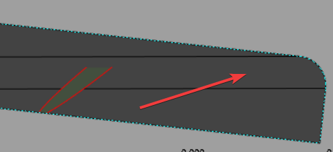
I made a similiar model as yours using an arbitrary crack and I see a similar rise in the SIF value with mesh refinement. I tested with UMM off but it doesn't significantly remedy the issue. Part of the issue has to do with the geometry; the sharp corner is causing a stress concentration at the extremeties of the crack. Modifying the geometry so that there is a slight round instead of the sharp edge seems to help (e.g., I used the Pull tool in SpaceClaim to make the edge into a round):
Still, the SIF value rises, but not as much as before. In contrast, J integral seems to converge much better. See the two parametric study results below, where the Front Element Size is, in descending order, a/10, a/25, a/33, a/50, a/100:
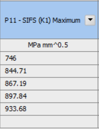
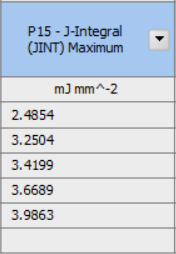
For the SIF case, I am still investigating why this doesn't converge. I hope to follow up soon with more information on this.
-
November 8, 2023 at 8:58 pm
Benedikt Huber
SubscriberHi David,
how did you mesh the round edge ? And where on the round contour does your crack exactly start ?
Thanks for your help !
-
-
-
- The topic ‘arbitrary crack as a weld root crack’ is closed to new replies.


-
5159
-
1836
-
1387
-
1249
-
1021

© 2026 Copyright ANSYS, Inc. All rights reserved.

