-
-
February 22, 2023 at 11:45 am
Wavebeaker101
SubscriberHello everyone!
I am doing a hydrodynamic diffraction analysis in Aqwa 2022.
The body i am researching in is a cylinder, which is floating close underneath the water surface(-0,02m). I defined a speed of 0,75 m/s and a wave direction of 180°.
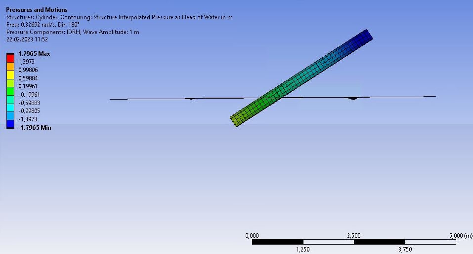
The results are not as expected. I am wondering about the movement of the body at low frequencies. In the RAO RY it has its peak at 0,32 rad/s with a value of 32,7° which leads to extreme rotation around the y-axis. The movement in z has its peak at the lowest frequency, 0,1 rad/s with a value of 4,07. Both is far to high and shown in the picures below. I expected both peaks somewhere at 3,77 rad/s where the wavelength equals the body length. At very low frequencies it should just follow the waterlevel without rotation.
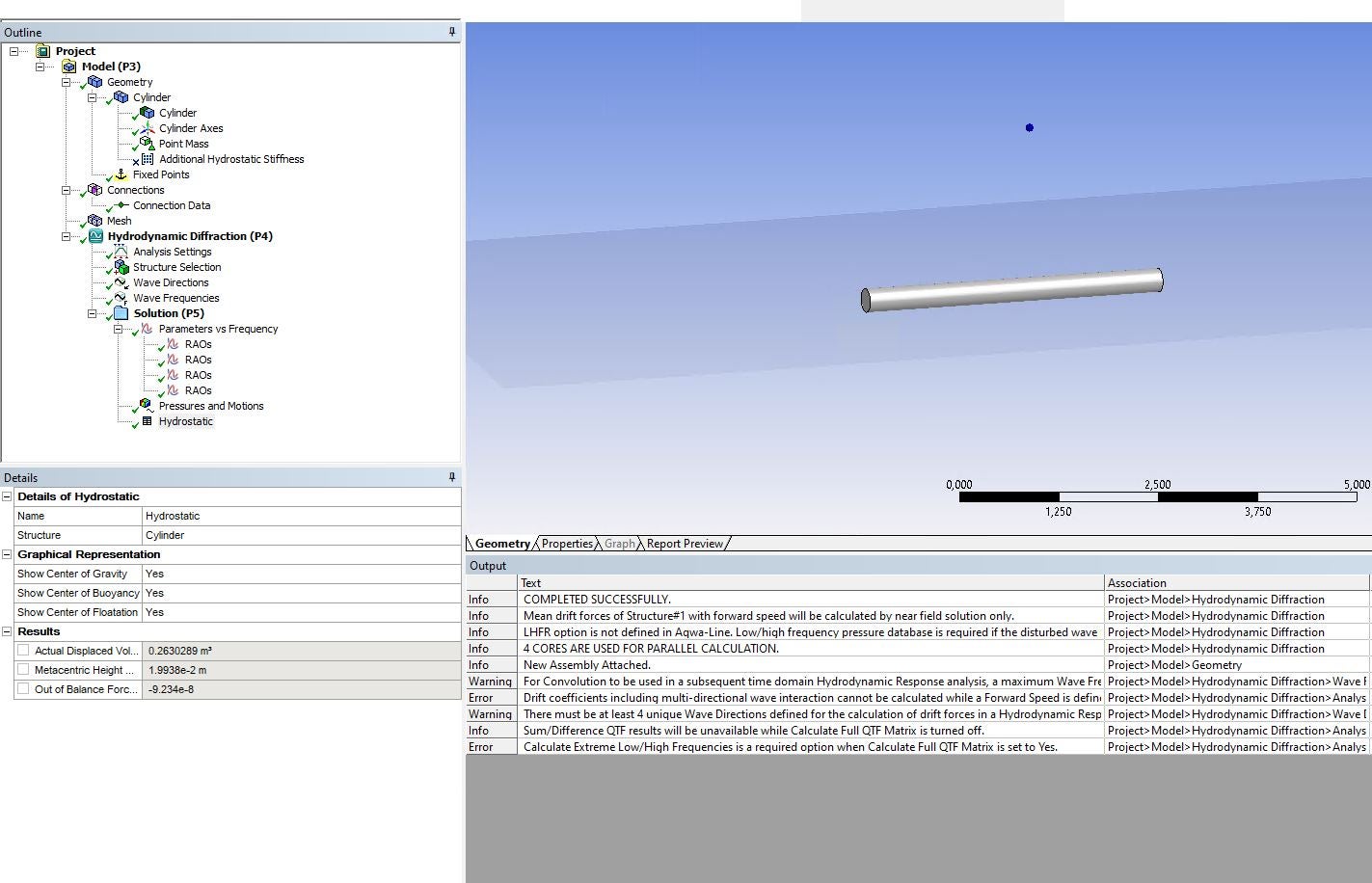
It follows the case' setup.
The technical specifications are L=4m,D=0,3m, m=289 kg (calculated by hand). The Center of Gravity has its position at x=0m; y=0; z=-0,19m. The center of buyancy is at x=0m; y=0; z=-0,17m.
First i draw the cylinder as a solid in Ansys Design Modeler, than I converted it to a thin geometry with the wallthickness of 0 m. Next step was shifting the cylinder so that the leading edge is on x=2m; y=0 and the cylinders symmetry axis lies at z=-0,17 and parallel to the global x-axis. \\
In Aqwa I included a pointmass with the mass calculated by aqwa due to the strctures position, and manually setting the z Position of the Center of Gravity. Which reads then x=9,36E-5m; y=1,5E-4m, z=-0,19m and 269 kg, which is 20,2 kg to less. Furthermore I added the mass moment of intertia Ixx=3,6 kgm^2,Iyy=Izz=388kgm^2, calculated by assuming the cylinder as a solid and the density of 1025kgm^-3. Meshing has been done by the Aqwa mesher with an element size of 0,1 m gives 418 elements.The analysis settings read generate wave grid pressures: Yes; Wave Grid resolution: Fine, Wave grid factor:2;
Calculate Extreme low frequencies: no;
Include multi-Directions: No;
Near Field Solution: Programm controlled;
Calculate Full QTF Matrix:No and all output file Options to no;
wave direction to 180° and a forward speed of 0,75 m/s.
25 wave frequencies in the interval of 0,1 rad/s to 6 rad/s.environment constraints:
Waterdepth: 1000 m
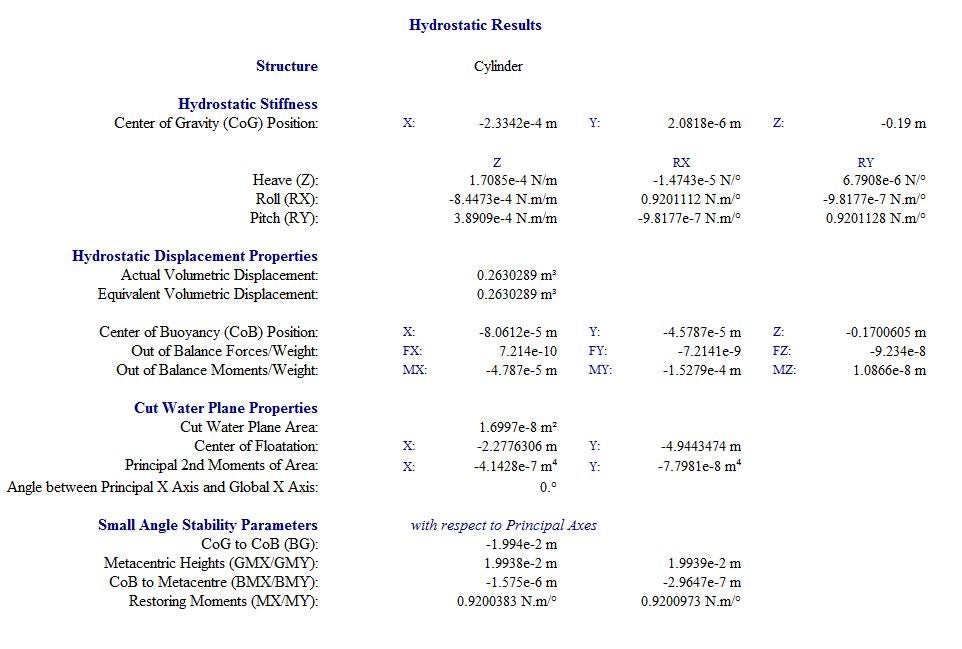
Water density: 1025 kgm^-3Analysing Hydrostatic Results (shown in the last picture):
I guess that the huge movement is related to the low restoring moment at small angles of 0,92 Nm/° in MX/MY and that the distance GoG to GoB (BG) is small and negative with a value of -0,01994 m. Why negative? The values for COB and COG are correct. Furthermore I am wondering that it calculated the center of flotation at x=-2,28m, y=-4,49 m. But there is simply no center of flotation because its fully submerged.
If anybody has an idea what is the solution here I am very thankfull.
Cheers
-
February 24, 2023 at 4:36 pm
Yu Bi
Ansys EmployeeHi, as the model is a fully submerged body, all the elements of the hydrostatic stiffness matrix should theoretically zero; the non-zero values in the Hydrostatic Results report are mainly due to the coarse meshes and the numerical truncated error. Please check if using refiner mesh could help. Besides, as it is a fully submerged body, the center fo floatation listed in the Cut Water Plane Properties data group has no meaning, no worry about these values.
The large RAOs in the low-frequency region could be understandable. At the low frequency, the inertial force/moment due to structure mass and added mass are very small, and there is no hydrostatic stiffness, any small wave exciting force/moment could generate large linear RAOs of the rigid body motions.
It is suggested that the nonlinear time-domain (Hydrodynamic Response in Irregular/Regular waves) hydrodynamic response analysis should be carried out, in which the instantaneous wetted surface will be used at each time step to calculate the nonlinear Froude-Krylov force and hydrostatic force, the responses will be more accurate for a body close to the mean water surface. To do so, you may need to use either the soft mooring lines or the course control system (for example a PID approach) to keep the structure in the required heading.
Besides, for the submerged surface that is very close to the mean water surface, it'd be better to have the element size smaller than the depth of the surface. Otherwise, there could be large numerical errors.
-
- The topic ‘Aqwa Diffraction Analysis: Submerged Cylinder does behave wrong’ is closed to new replies.


-
3387
-
1052
-
1050
-
886
-
857

© 2025 Copyright ANSYS, Inc. All rights reserved.


