-
-
July 25, 2018 at 6:06 pm
Sepi
SubscriberHello everyone,
So I am doing a static(quasi-static) analysis and I want to apply the load in my model on a set of nodes in form of displacements that gradually increase with each load step, like a ramp. It means I want to start from u_x=0 at these nodes and apply an additional amount of delta_u_x in each load step until I reach the ultimate value for it.
Like: Start: u_x=0
Go up in a ramp of 10 load steps, in each increment add 1 unit to u_x
Finish u_x=10
Please could you let me know how I should do this.
Thanks a lot.
Sepideh
-
July 25, 2018 at 6:24 pm
peteroznewman
SubscriberHello Sepi,
Apply a displacement of 10 mm to the face or edge that you want to move.
Under Analysis Settings
Under Step Controls, change Automatic Time Stepping to On
Initial Substeps 10
Minimum Substeps 10
Maximum Substeps 100
further down,
 turn on Large Deflection.
You should get exactly 10 substeps of 1 mm each unless the solver has difficulty converging, then you might get extra substeps.
Regards,
Peter
-
July 25, 2018 at 6:32 pm
-
July 25, 2018 at 7:45 pm
peteroznewman
SubscriberSepi,
There are two ways to accomplish what you want, Sandeep shows a method that will give you results at exactly the 1 mm increments, while the method I described might give you that, but could give you results off the 1 mm marks.
But in either case, turn on the Large Deflection setting.
Peter
-
July 26, 2018 at 3:06 pm
Sepi
SubscriberHi Sandeep,
Thank you for your reply. I have to admit that I do not know how to create a table which assigns values for the displacement at specific load sub-steps.
What I am doing is that I have to implement my own models in an open source software, but I also want to set up a quick model in ANSYS to do a double check of the results of my own program with ANSYS.
Thanks
Sepideh
-
July 26, 2018 at 3:09 pm
Sepi
SubscriberHi Peter,
Thank you so much. It seems to be working. However, I still have an additional question: I want to plot the reaction forces vs displacement at the nodes where I am applying the displacement load. I have no clue how I can save these data for each substep in form of a table or array which I can later use for plotting. Do you have any suggestions for me?
Thanks.
Sepideh
-
July 26, 2018 at 4:15 pm
Sandeep Medikonda
Ansys EmployeeHi Sepideh,
You might find this page from the manual helpful.
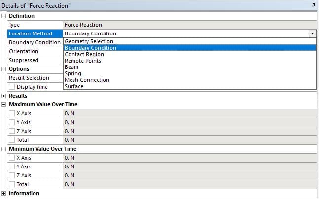
You can also calculate the force reaction as shown here:
and then scope it according to what you need:
For plotting force vs displacement, check out this post from earlier today.
Regards,
Sandeep
-
- The topic ‘Applying ramped displacement load in static analysis’ is closed to new replies.


- The legend values are not changing.
- LPBF Simulation of dissimilar materials in ANSYS mechanical (Thermal Transient)
- Convergence error in modal analysis
- APDL, memory, solid
- How to model a bimodular material in Mechanical
- Meaning of the error
- Simulate a fan on the end of shaft
- Nonlinear load cases combinations
- Real Life Example of a non-symmetric eigenvalue problem
- How can the results of Pressures and Motions for all elements be obtained?

-
3862
-
1414
-
1221
-
1118
-
1015

© 2025 Copyright ANSYS, Inc. All rights reserved.


