-
-
July 14, 2019 at 3:31 pm
HamzaBaqasah
SubscriberHello everyone,
I'm trying to simulate a cantilever beam that is fixed from one end and free from the other end.
From the fixed end, I want to apply a displacement at certain frequency (such as 30Hz at +/- 0.4 mm).
by harmonic analysis, what kind of load should I apply here? is it displacement? but then how can I adjust the frequency?
Â
Appreciate your help as I'm recent user of ANSYS workbench.
Â
Regards,
Hamza
-
July 15, 2019 at 12:15 am
peteroznewman
SubscriberAn efficient way to do this, if you can accept a linear model, is to create a Modal analysis and drop a Harmonic Response onto the Solution cell of the Modal. That will allow you to apply an Acceleration as a Base excitation on the Fixed Support. Just convert the displacement specification of +/-0.4 mm at 30 Hz to the equivalent 14.2 m/s^2 acceleration. In the Analysis Settings, specify the frequency range, for example 25 - 35 Hz with 10 steps.
An ANSYS 2019 R2 archive is attached.
-
July 28, 2019 at 10:47 pm
-
July 29, 2019 at 3:37 am
peteroznewman
SubscriberPick a vertex on the geometry where you expect to see a significant response. In the Harmonic Response system, under the Solution Branch, insert a Frequency Response for Acceleration, Velocity or Displacement. That will generate an amplitude of response vs frequency plot.
-
July 29, 2019 at 8:04 pm
HamzaBaqasah
SubscriberHi Peter,
Â
Thanks for your reply I could find the amplitude but it's not reasonable may be due to my inputs.
Could you please the first image that shows my inputs in acceleration details? also, in the second image, the arrow is only directing to the top where my shaker is going up and down.
Best regards,
Hamza
Â
Â
-
July 29, 2019 at 8:43 pm
peteroznewman
SubscriberWhat is the displacement result? What do you think is a reasonable value?
Please attach a .wbpz archive file of your project so I can take a closer look.
-
July 29, 2019 at 8:57 pm
HamzaBaqasah
SubscriberThe amplitude value is very high compared to the length of the beam.
Second, the arrow is only directing towards the top. I don't know if it's okay since I want to simulate the shaker where it moves up and down.
Â
The project file is attached.
-
July 29, 2019 at 9:48 pm
HamzaBaqasah
SubscriberDear Peter,
I'm afraid my project file is too large to be uploaded in this website.
-
July 29, 2019 at 10:43 pm
HamzaBaqasah
SubscriberDear Peter,
This is GoogleDrive link so you can download my project file.
https://drive.google.com/file/d/1gTc8LeMnrwYBS-0hZK7b53B-NykxlNkt/view?usp=sharing
Thanks,
Hamzah
-
July 30, 2019 at 2:52 am
peteroznewman
Subscriber
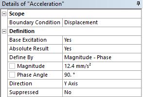
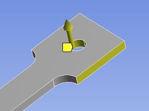
The acceleration arrow direction is for up and down along that axis.
Your model has a mistake, the acceleration is 14.2 m/s^2Â You typed 12.4 mm/s^2.
Insert a Frequency Response for Displacement of a vertex at the fixed end and you will see the 0.4 mm amplitude at 30 Hz.
The amplitude is high because you did not include any Damping in the model.
You have to enter some amount of damping, say Damping Ratio = 0.01 = 1%
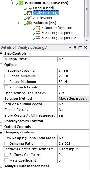
With 0% Damping Ratio, there is a 267 mm displacement at the tip at 24 Hz.
With 1% Damping Ratio, there is a 48.7 mm displacement at the tip at 24 Hz.
With 2% Damping Ratio, there is a 24.7 mm displacement at the tip at 24 Hz.
Keep in mind that this is a linear analysis. When the deflections get too large, the small rotation assumption in the linear model is no longer valid. In that case, you have to perform a Full Transient and turn on Large Deflection in order to see the true deformation.
Also, Insert a Mesh Control Method called Multizone on the body.
-
July 30, 2019 at 8:47 pm
HamzaBaqasah
SubscriberHi Peter,
Thanks for your help I appreciate that.
I just need to know the amplitude when running it at its natural frequency and I think this gives me an idea especially when I want to compare it with another same geometry but has higher crack depth.
another question is does phase angle effects the results? I have used 90 degrees. should it be 0?
Â
Regards,
Hamzah
-
July 31, 2019 at 12:54 am
peteroznewman
SubscriberIn your case, since there is only one load, the phase angle is irrelevant, 0 and 90 give the same answer.
Phase angle matters when you have two or more loads and you want to specify if they are in sync or out of sync.
-
July 31, 2019 at 9:52 am
HamzaBaqasah
SubscriberThank you Peter. That was very helpful!
-
- The topic ‘Applying External vibration (shaker simulation)’ is closed to new replies.
-
4838
-
1587
-
1386
-
1242
-
1021
© 2026 Copyright ANSYS, Inc. All rights reserved.


