-
-
October 18, 2023 at 12:56 pm
-
October 18, 2023 at 4:38 pm
Amrita Pati
Ansys EmployeeHi,
The default auto non-uniform mesh in FDTD generates mesh based on the refractive indices of the material (along with other factors). The effective wavelength of EM fields is shorter in high index materials, so, the algortithm automatically generates smaller mesh which implies that the density of the meshing is higher. And then as you go from higher-index material to lower-index material the mesh doesn't change suddenly but rather in a gradual/graded manner, which is also decided by the algorithm.Â
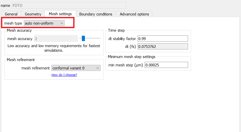
So, if you have chosen the default "auto non-uniform" mesh, the mesh should be graded at the interfaces of materials with different indices. With "custom non-uniform" you can also change the grading factor.
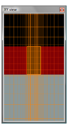
From your screenshot it seems to me that you have either used uniform mesh, or mesh override region, which is why the mesh is not graded but rather uniform. Is that the case?
Regards,
Amrita -
October 19, 2023 at 2:20 am
Altair45
SubscriberThanks for your response.
I make the 'mesh override' disable and recalculate the mesh but, there are still no graded mesh applications in my structure. Also, the "auto non-uniform' is set up.
As you mentioned, the reason is related to the difference in refractive index between the Si and SiO2. Isn't it? -
October 19, 2023 at 5:22 pm
Amrita Pati
Ansys EmployeeYes, that is correct. As Si and SiO2 have different indices, the mesh density will be higher in Si than in SiO2. And there will be grading near the interfaces. Are you re-meshing the simulation domain after you disable the meshoverride region?
Also, I think you should be able to see a higher contrast between the two regions if you increase the mesh accuracy. So, increase the mesh accuracy, remesh, and see if that makes a difference.Â
Regards,
Amrita
-
- The topic ‘application of graded mesh’ is closed to new replies.
-
3462
-
1057
-
1051
-
918
-
896
© 2025 Copyright ANSYS, Inc. All rights reserved.