-
-
March 21, 2025 at 7:39 pm
peteroznewman
SubscriberI am just starting to learn MAPDL. Hopefully this is a simple question.
In MAPDL a volume was created using BLOCK. A mesh of CPT215 hex elements were created by VSWEEP between two AREA IDs of that volume using MATID 1. I create a mesh of SHELL181 elements on 3 AREAs of that volume and am trying to use MATID 4 for those to change from a porous material to a non-porous hyperelastic material. I have some APDL code below to look at. When I read this file into Mechanical APDL, I get an error. Shell element 1063 does not have a valid section ID or real constants.
This is a follow-on question to this discussion: https://innovationspace.ansys.com/forum/forums/topic/pore-pressure-analysis-with-cpt215-elements-porous-elasticity-and-pm/
finish
/clear
! units of mm kg and N
/TITLE, PorousElastic_PM_Skin
/prep7
ET,1,CPT215
keyopt,1,12,1
TB,PELAS,1,1,,POISSON
TBDATA,1,0.1,10,0.1,0.45
FPX=0.1e-2
TB,PM,1,,,PERM
TBDATA,1,FPX
ETABLE,p_pres,PMSV,PPRE
! create and mesh geometry
block,,80,,20,,6
cyl4,20,,6,,,,6
cyl4,60,,6,,,,6
vsbv,1,all
VSEL,ALL
MSHAPE,0,3D
ESIZE,2
VSWEEP,4,18
! Define a new material and create a skin of elements on 3 faces of the volume.
TB,HYPE,4,1,1,NEO
TBDATA,1,0.003,50000000
ET,4,SHELL181
keyop,4,1,1         ! Membrane stiffness only
SECTYPE,4,SHELL ! Define shell section
SECDATA,1.0,4 ! Define section data, THICKNESS, MATID
ASEL,S,AREA,,4,6,1
AMESH,ALL,
esel,all
! apply symmetry BCs
nsel,s,loc,y,0
d,all,uy
nsel,s,loc,z,0
d,all,uz
! fix one node in x
nsel,r,loc,y,0
nsel,r,loc,x,0
d,all,ux
! apply pressure loads to areas 9 and 13
pp_inlet=1.1
pp_outlet=1.0
SFA,9,1,PRES,pp_inlet
SFA,13,1,PRES,pp_outlet
finish
/solu
antype,0             ! static analysis
nlgeom,on            ! Turn on Large Deformation
eqsl,sparse,,,,,1
solve
autots,on            ! Turn on auto time stepping
nsub,20,1000,10,OFF
time,1.
finish
!/view,1,1,2,3
!/expand,1,rect,half,0,0,-1e-6
!/expand,2,rect,half,0,-1e-6,0,2,rect,half,0,0,-1e-6
/post1
set,last
!plesol,s,eqv
esel,all
ETABLE,p_pres,PMSV,PPRE
ETABLE,f_flux_x,FFLX,X
ETABLE,f_flux_y,FFLX,Y
ETABLE,f_flux_z,FFLX, -
March 22, 2025 at 11:49 am
peteroznewman
SubscriberThanks to Erik for help fixing the error in the code above. I was missing a command to correctly set the section properties. The revised code is below, which will solve, however the outcome seems to be a solution where the results are all zero. I am not yet skilled at the Mechancial APDL GUI for investigating models and results, but it seems the pressure loads are no longer applied compared with the code block in this discussion which the etable vector plot for fluid flux reveals flow through the external faces. I am trying to prevent that in the code below with a skin of non-porous shell elements.
finish
/clear
! units of mm kg and N
/TITLE, PorousElastic_PM_Skin
/prep7
ET,1,CPT215
keyopt,1,12,1
TB,PELAS,1,1,,POISSON
TBDATA,1,0.1,10,0.1,0.45
FPX=0.1e-2
TB,PM,1,,,PERM
TBDATA,1,FPX
ETABLE,p_pres,PMSV,PPRE
! create and mesh geometry
block,,80,,20,,6
cyl4,20,,6,,,,6
cyl4,60,,6,,,,6
vsbv,1,all
VSEL,ALL
MSHAPE,0,3D
ESIZE,2
VSWEEP,4,18
TB,HYPE,4,1,1,NEO
TBDATA,1,0.003,50000000
ET,4,SHELL181
keyop,4,1,1         ! Membrane stiffness only
SECTYPE,4,SHELL ! Define shell section
SECDATA,1.0, ! Define section data: THICKNESS
SECNUM,4
MAT,4
ASEL,S,AREA,,4,6,1
AMESH,ALL,
esel,all
! apply symmetry BCs
nsel,s,loc,y,0
d,all,uy
nsel,s,loc,z,0
d,all,uz
! fix one node in x
nsel,r,loc,y,0
nsel,r,loc,x,0
d,all,ux
! apply pressure loads to areas 9 and 13
pp_inlet=1.1
pp_outlet=1.0
SFA,9,1,PRES,pp_inlet
SFA,13,1,PRES,pp_outlet
finish
/solu
antype,0             ! static analysis
nlgeom,on            ! Turn on Large Deformation
eqsl,sparse,,,,,1
solve
autots,on            ! Turn on auto time stepping
nsub,20,1000,10,OFF
time,1.
finish
!/view,1,1,2,3
!/expand,1,rect,half,0,0,-1e-6
!/expand,2,rect,half,0,-1e-6,0,2,rect,half,0,0,-1e-6
/post1
set,last
!plesol,s,eqv
esel,all
ETABLE,p_pres,PMSV,PPRE
ETABLE,f_flux_x,FFLX,X
ETABLE,f_flux_y,FFLX,Y
ETABLE,f_flux_z,FFLX,Z -
March 24, 2025 at 4:00 pm
dlooman
Ansys EmployeeYou shouldn't need to artificially block the flow. If there's no boundary condition, the flux should be parallel to the surface. FSUM on sample surface nodes confirms there's no flow there. Perhaps there is a non-zero flux at the centroid of the elements.
-
March 24, 2025 at 10:18 pm
peteroznewman
SubscriberThanks Dave, that's a helpful observation! I'm going to abandon the skin elements for now and go back to the simple porous block.
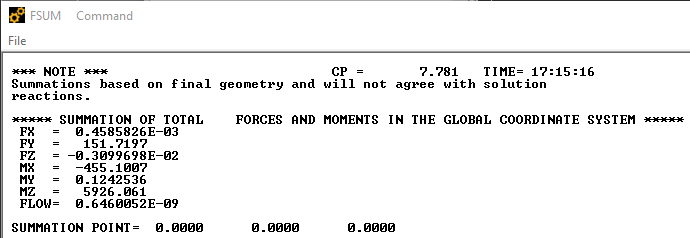
If I select everything and use the FSUM command, I get this listing:
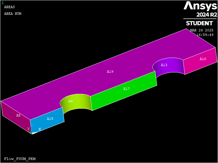
I would like to output the FSUM listing for areas 9 and 13 separately.
The last 3 lines of code gives the same listing for the everything listing above, but perhaps I don't yet understand selection logic.
finish
/clear
/TITLE, Flow_FSUM_PEM
/prep7
ET,1,CPT215
keyopt,1,12,1
TB,PELAS,1,1,,POISSON
TBDATA,1,0.1,10,0.1,0.45  ! units of mm kg N
FPX=0.1e-2
TB,PM,1,,,PERM
TBDATA,1,FPX
block,,80,,20,,6  ! create and mesh geometry
cyl4,20,,6,,,,6
cyl4,60,,6,,,,6
vsbv,1,all
VSEL,ALL
MSHAPE,0,3D
ESIZE,2
VSWEEP,4,18
nsel,s,loc,y,0    ! apply symmetry BCs
d,all,uy
nsel,s,loc,z,0
d,all,uz
nsel,r,loc,y,0    ! fix one node in x
nsel,r,loc,x,0
d,all,ux
pp_inlet=1.1      ! apply pressure to areas 9 and 13
pp_outlet=1.0
SFA,9,1,PRES,pp_inlet
SFA,13,1,PRES,pp_outlet
allsel,all
finish
/solu
antype,0             ! static analysis
nlgeom,on            ! Turn on Large Deformation
eqsl,sparse,,,,,1
solve
autots,on            ! Turn on auto time stepping
nsub,20,1000,10,OFF
time,1.
finish
/view,1,1,2,3
/post1
set,last
esel,all
ETABLE,p_pres,PMSV,PPRE
ETABLE,f_flux_x,FFLX,X
ETABLE,f_flux_y,FFLX,Y
ETABLE,f_flux_z,FFLX,Z
ASEL,S,AREA,,9,9
NSEL,ALL
FSUM -
March 25, 2025 at 3:35 pm
dlooman
Ansys EmployeeAfter selecting an area you select the nodes of that area with nsla,s,0 if you only want the nodes interior to the area and nsla,s,1 if you want all the nodes associated with the area, including the edges. In this case you may want to use nsla,s,0 to avoid picking up flow from and adjacent area.
-
- You must be logged in to reply to this topic.


-
5149
-
1836
-
1387
-
1248
-
1021

© 2026 Copyright ANSYS, Inc. All rights reserved.


