-
-
August 31, 2024 at 10:45 am
Sean Hanna
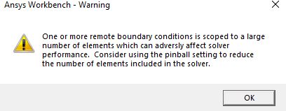
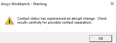
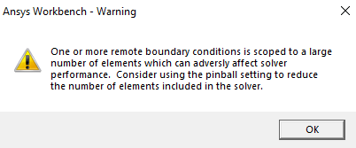
SubscriberHello Im having issues with how to set up contacts and joints and boundary conditions for a differential gearbox design in order to simulate it being driven at a constant rpm from the engine but the wheels are cornering and so power is transfered to the other wheel. currently I am using transient structual solver and have managed to get a small rotation to function but it fails when increasing the rotation amount and im not sure if these boundary conditions meet my criteria for an accurate open differental simulation. additionally im often getting the following errors.
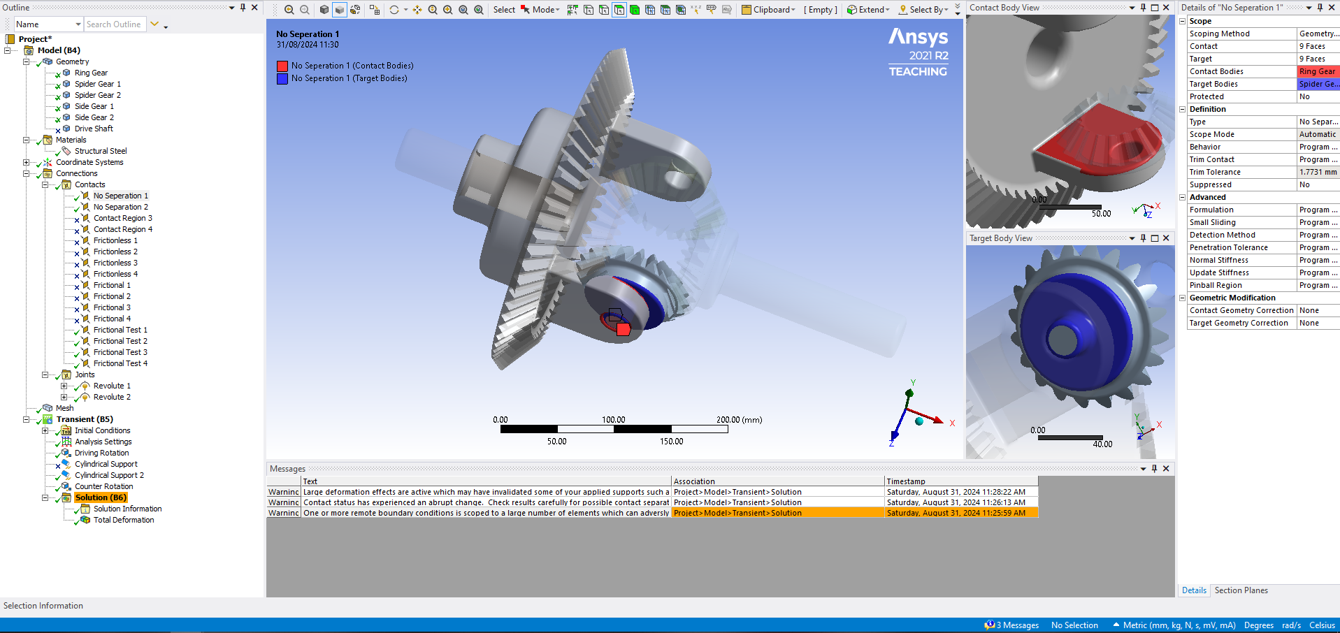
My contacts are as follows.
Contact between the bracket and the spider gear, this could possibly be surpressed.
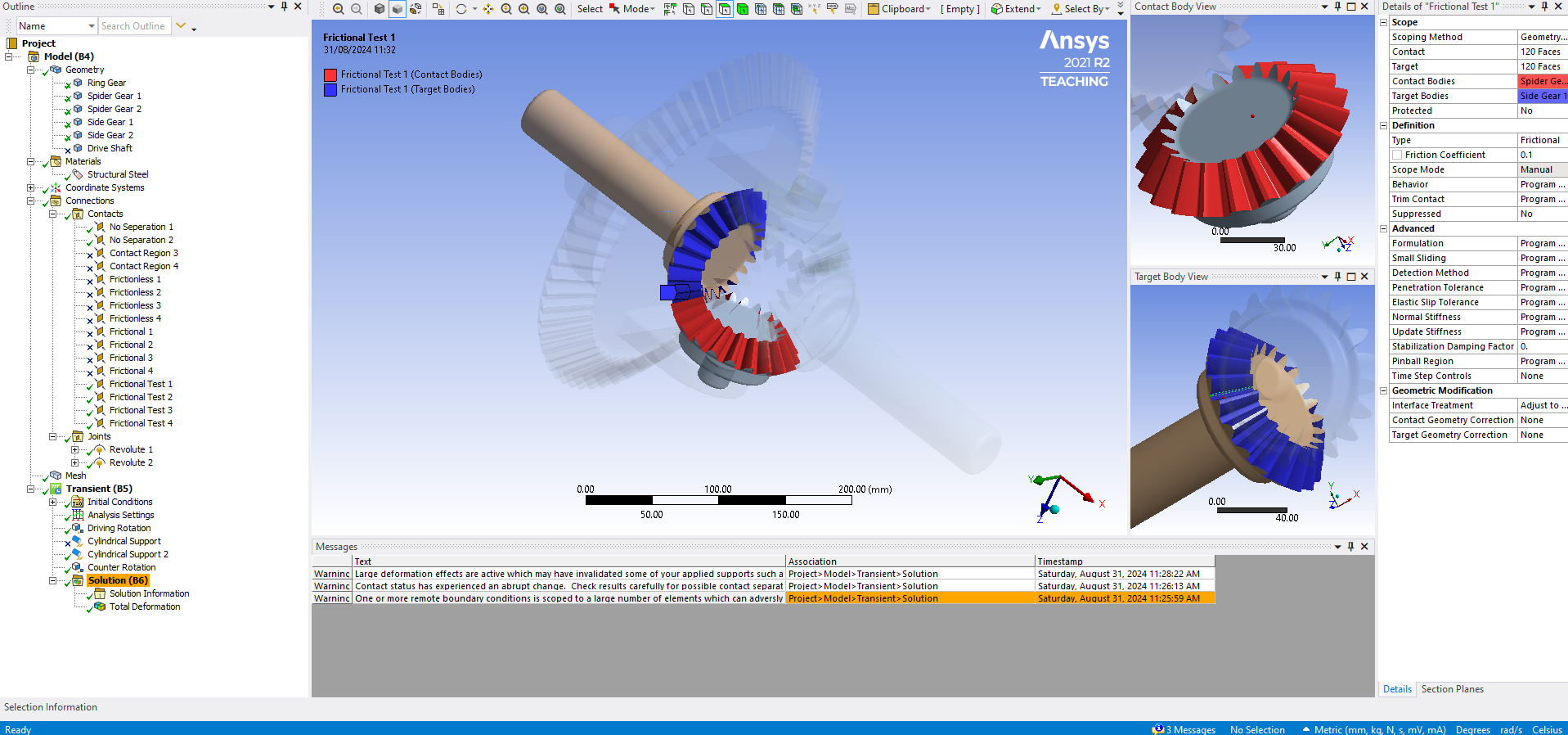
gear-gear teeth contacts, this is the same for all 4 interfaces.
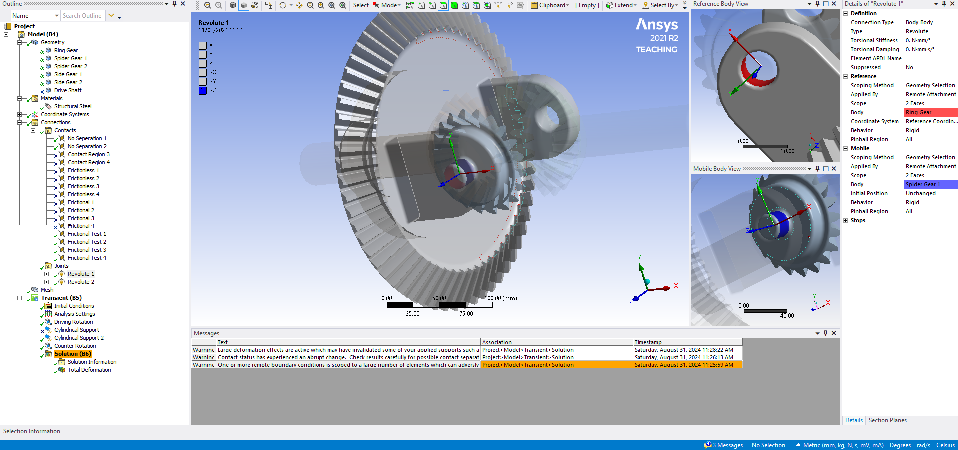
Revolute joint settings are the same for both bracket-spider gear interfaces
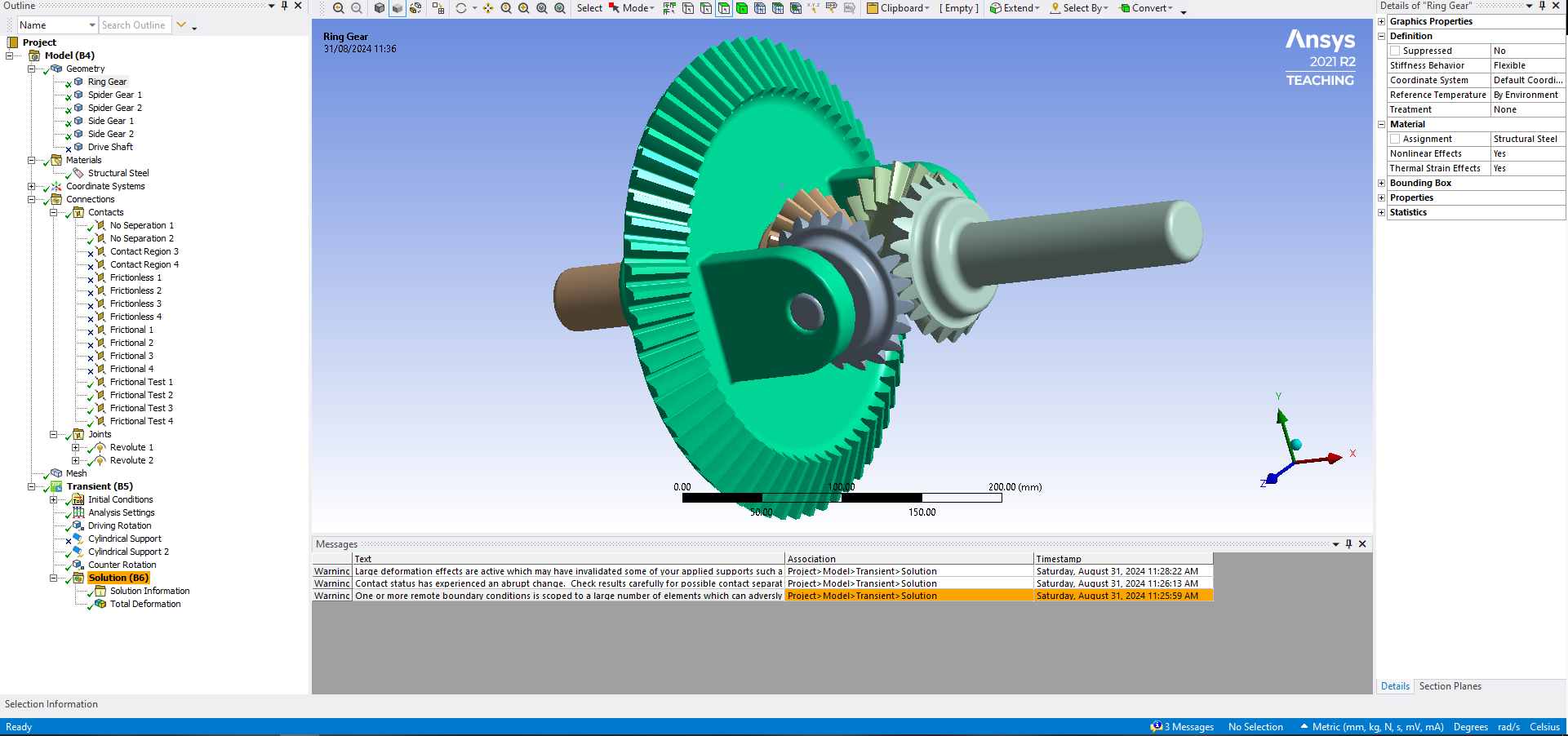
overall geometry settings. material is kept constant.
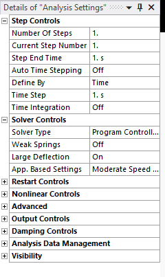
analysis settings
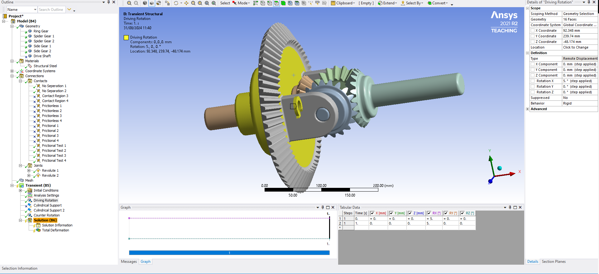
location and size of the driving rotation from the drive shaft, this is a remote displacement on the selected area.
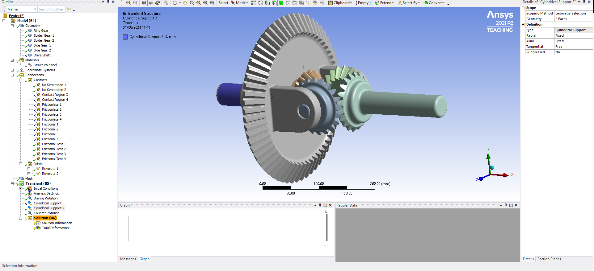
Left wheel set as a cylindrical support.
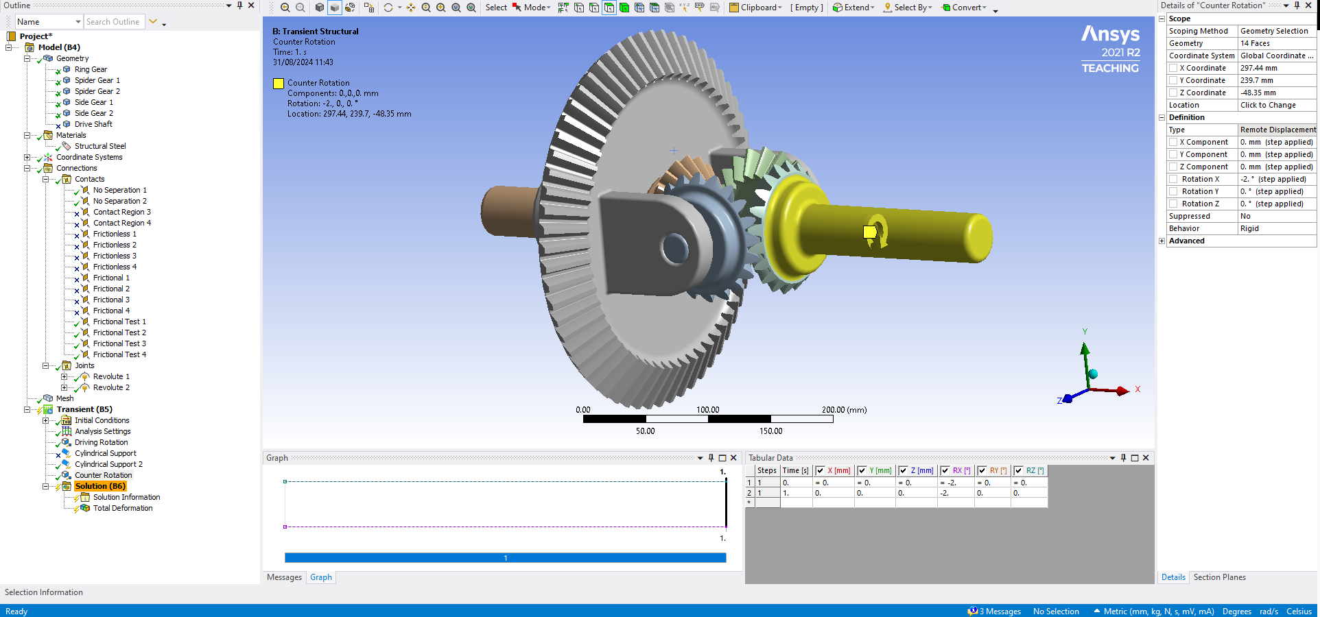
Counter rotation meant to simulate friction or resistance caused by this being the inside wheel that is turning. this also a remote displacement.
-
September 1, 2024 at 7:42 pm
peteroznewman
SubscriberI watched this video to get the terminology of the different gears in the assembly.
I suggest you initially setup the differential gearbox as a static structural analysis. The ends of each wheel axle are fixed. Instead of applying a rotation input to the ring gear, apply a torque. Multiply the engine torque by the gear ratio of ring gear to pinion gear (not modeled). The static solution will give the stress in the teeth as well as the arm holding the spider gear.
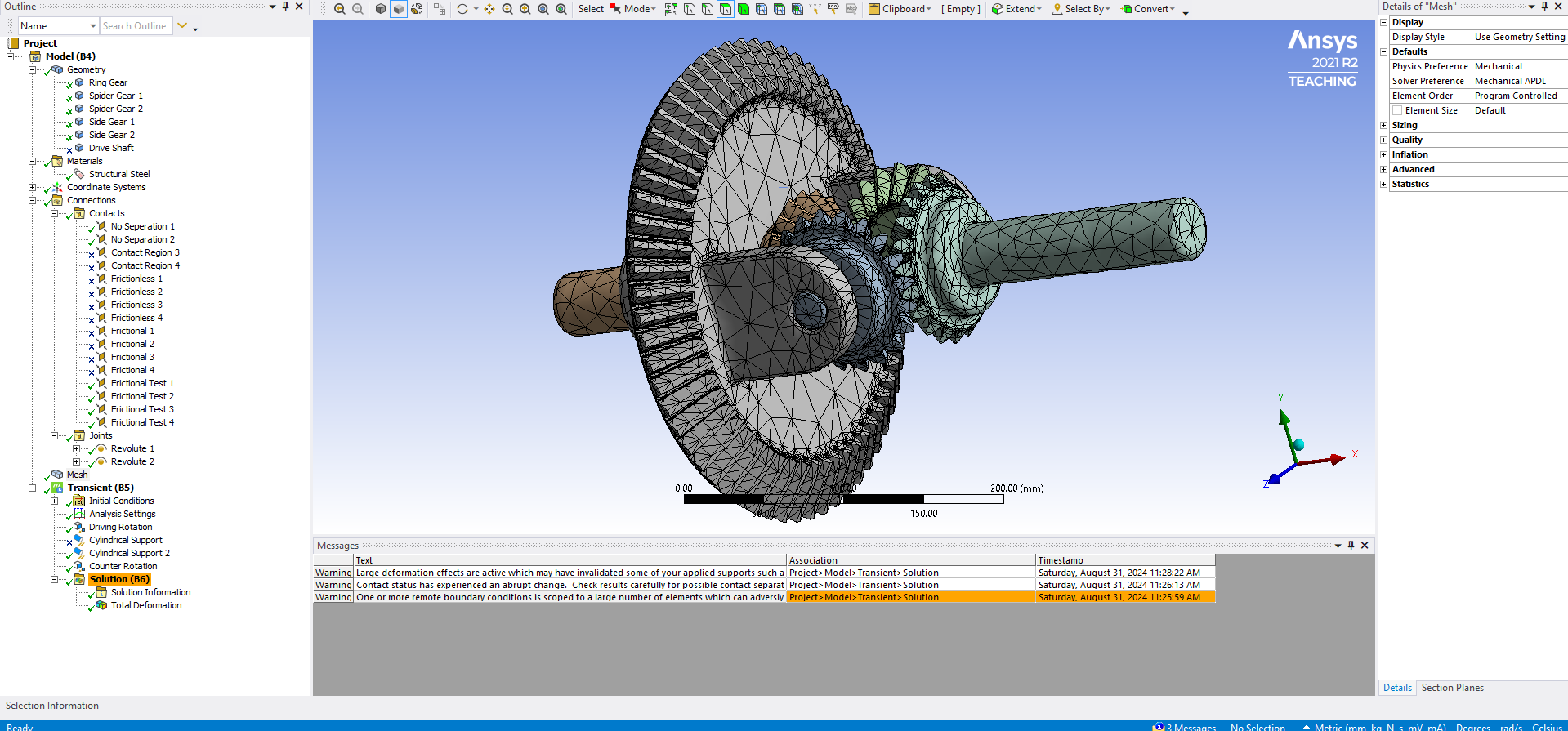
The benefit of a static solution is that it will be much easier to achieve convergence. Also, you should increase mesh density at the contact points of the spider gears and side gears. This will give much more accurate stress results in the teeth.
-
- You must be logged in to reply to this topic.


-
4959
-
1639
-
1386
-
1242
-
1021

© 2026 Copyright ANSYS, Inc. All rights reserved.

