TAGGED: constraints, fea, solver-limitations
-
-
October 19, 2021 at 10:41 am
Toby_Jones
SubscriberHi,
I am outlining a benchmark style study for ansys sherlock - this will include a functional test to compare against the output from sherlock. I am limited in testing time, but can consider a highly accelerated approach for real-life testing.
To ensure I am accurately representing the output(s) of sherlock, are there limitations to the FEA model and is there a particular range that the model is tuned for? (ie does the model still output accurate results if components are knowingly put near or beyond their design limits, minimum duration for a reliability study, any constraints of the simulation approach.)
Any further information on how Sherlock computes the overall reliability score, and the inputs that the model takes from the component library would be incredibly helpful.
Kind Regards
Toby
October 22, 2021 at 3:50 pmDavid Dang
Ansys EmployeeHi Toby Thank you for submitting your question.
The answer to your question will to some degree depend on the type of fatigue failure you're trying to model. Thermal cycling vs Vibration; low cycle vs high cycle fatigue. However Sherlock will be able to compute a time to failure and reliability score. In terms of limitations of the model, the FEA model is linear and we do not necessarily explicitly model the all solder joints, however more detailed analysis can be achieved by combining Sherlock with Ansys Mechanical.
If you would like to discuss this in more detail, feel free to submit an SR through the support.ansys.com.
Thanks David Dang
Senior Application Engineer, Ansys Inc.
October 26, 2021 at 12:20 pmToby_Jones
SubscriberHi David
Thank you for your response -
The area of most interest to me was thermal cycling (manifesting as mechanical stress on components with different CTE's).
I aim to build a thermal profile using AEDT to serve as an input for sherlock. This would generate the expected service temperatures at low and high load operating points for the PCB.
The output of this (I was hoping) would be a reliability score based on the thermal load profile, which I could test and validate (ie cycle the PCB til failure and compare predicted cycles against real cycles)
From Studying the theory documentation, it appears it looks at the temperature delta in the thermal profile, and computes based off this and the ECAD data/component library. It looks in 2021 R2 that a reliability score has been withdrawn when looking just at therm/mechanical loading - the documentation suggests the user can interpret the strain output for further reliability studies.
Do you have any suggestions on how to proceed? I am keen to keep the scope to just thermal cycling on the PCB, and really require a means of modelling predicted cycles to failure. At a stab, I presume I could look at the reported strain from each component in sherlock, assume bulk material properties at each interface, and put on a SN curve and indicate cycles til failure that way?
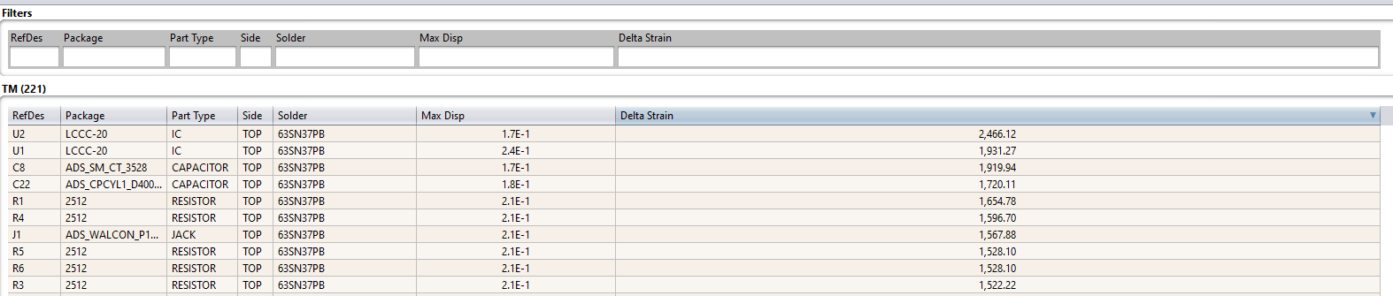
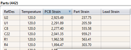
(the component data is taken from the example ODB++ -)
Kind Regards
Toby
Viewing 2 reply threads- The topic ‘Ansys Sherlock Constraints’ is closed to new replies.
Ansys Innovation SpaceTrending discussionsTop Contributors-
3427
-
1057
-
1051
-
896
-
892
Top Rated Tags© 2025 Copyright ANSYS, Inc. All rights reserved.
Ansys does not support the usage of unauthorized Ansys software. Please visit www.ansys.com to obtain an official distribution.
-