-
-
January 4, 2024 at 9:30 pm
Adam Sandahl
SubscriberHi,
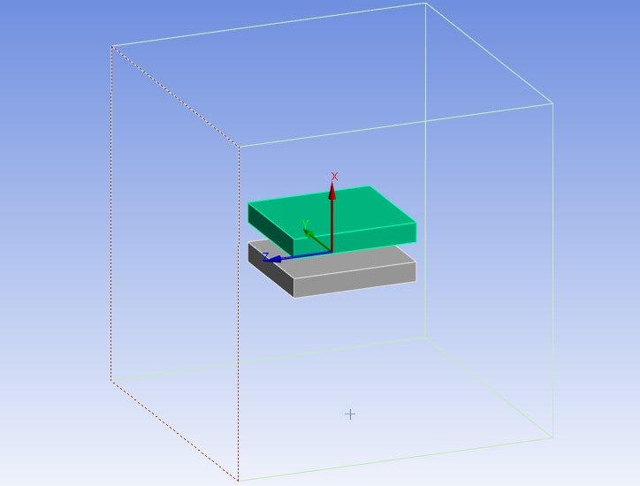
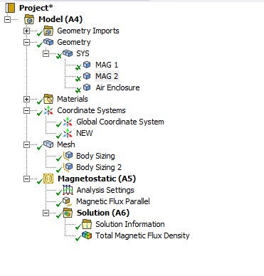
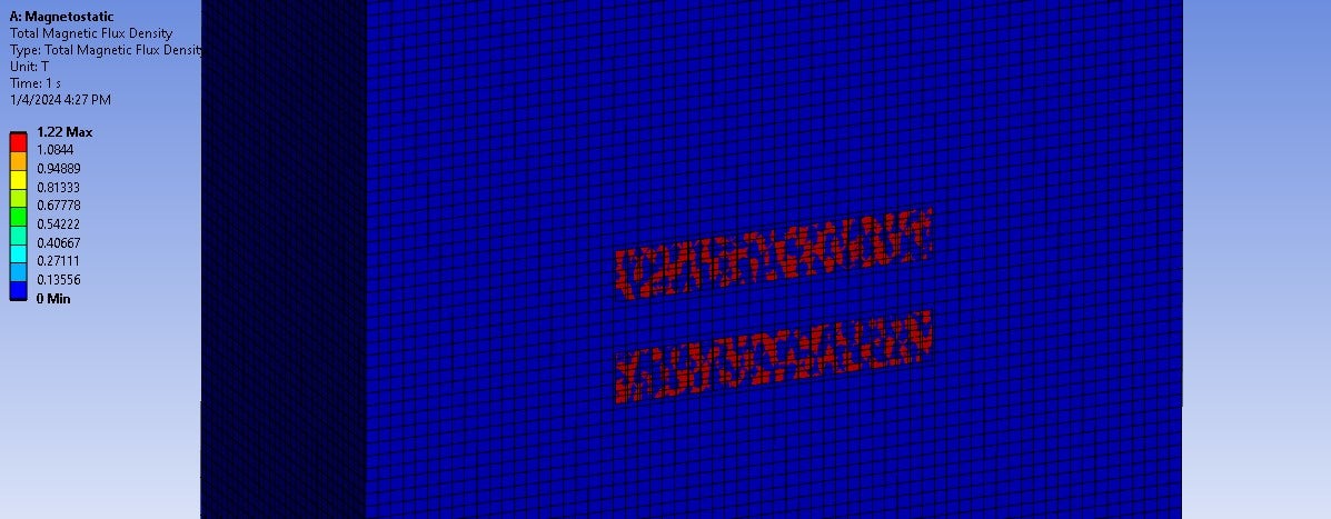
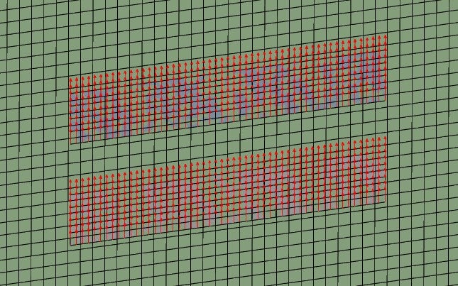
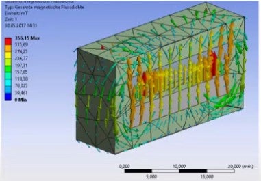
I was using Magnetostatic to simulate the magnetic flux density field between two permanent magents. I modeled the magnets in space claim with an enclosure of air and assigned them polarization in the positive (upward in this case) direction. However, when I solve, result doesn't seem to make sense as can be seen below. This is very confusing as I was following multiple tutorials online who all got flux density fields with seemingly correct vectors. There is no contour to the plot generated on the cross-section it is all either max or min. I also cannot draw a path between the magnets to find the peak magnetic flux density as the "path" feature and, all contruction geometry for that matter, is greyed out. Any insight here is greatly appreciated.
-
January 4, 2024 at 9:38 pm
Adam Sandahl
SubscriberFor context I am looking for something akin to the result below I am fairly sure my magents are polarized in the same way.
From this YouTube video: ANSYS Magnetostatic Permanent Magnet Parameter Study
-
- The topic ‘ANSYS Magnetostatic Permanent Magnet Question’ is closed to new replies.


-
4763
-
1565
-
1386
-
1242
-
1021

© 2026 Copyright ANSYS, Inc. All rights reserved.

