Hi Rabindra!
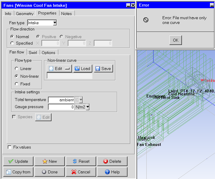
To shift the question a little bit: the necessity is to control the fan as a function of some external temperature or condition in a transient simulation. We are able to set up a transient fan, but what we wish to do is specify a fan curve, or setpoint, as a function of temperature to analyze transient behavior.
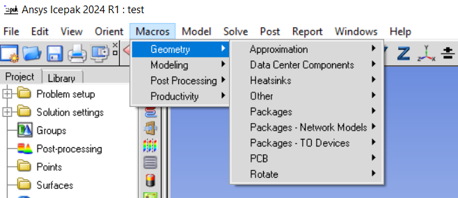
I cannot find in the documentation how to prepare a macro, as you mentioned. Is this something the user can do? If so, can you point me to where this would be located in the documentation or examples on the portal?