TAGGED: fluent, mrf, pump-impeller
-
-
January 23, 2026 at 10:15 pm
Matheus1.moreira
SubscriberHello everyone,
I am running a steady state MRF simulation in ANSYS Fluent of an axial flow pump at constant angular speed, but the results are consistently non physical: the pump behaves like a turbine. In all cases, the inlet pressure ends up higher than the outlet pressure (negative pressure rise), even though I am confident the impeller rotation axis and direction are correct.
What I observe
The solution converges (residuals drop and mass imbalance is small), but:
inlet pressure is higher than outlet pressure
the pressure field suggests energy extraction rather than addition
this happens systematically regardless of boundary condition choice
Boundary conditions tried
I tested multiple inlet and outlet boundary condition pairs:
Pressure inlet and mass flow outlet
Mass flow inlet and pressure outlet
Total pressure inlet and static pressure outlet
Static pressure inlet and static pressure outlet with different values
None of these configurations produces a physically reasonable positive pressure rise.
I can provide screenshots and values if needed:
mesh near rotor stator interface and y plus
pressure and velocity contours and streamlines
residuals and mass imbalance
angular speed, target flow rate and expected pressure rise
Thank you for any help or direction.
-
January 26, 2026 at 10:18 am
Petros
Ansys EmployeeHi, what value do you set at the outlet pressure bondary condition? Is the pump pushing fluid against gravity? Also how did you set a static pressure at the inlet?
A meridional picture of the mesh would help.
Â
-
January 28, 2026 at 5:06 pm
Matheus1.moreira
SubscriberI will answer by parts:
My simulation do not take into account gravity effects, but would not be a problem to add if it helps.
As boundary conditions I should do the whole caracterization of the pump from as I did in experiments from 6000 RPM to 15000 RPM from 0 to maximum 8 L/min with a newtonian fluid that have density of 1150kg/m^3 and 0,0048 as viscosity.Â
The condition that is more relevant to me is with 20 mmHg at the inlet and 160 mmHg at the outlet with 12000 RPM and 3 L/min.Â
I tried a lot of different conditions to simulate it
Mass inlet flow of 3L/min and Outlet Pressure of 0 at Gauge PressureMass inlet flow of 3L/min and Outlet Pressure of 160 at Gauge Pressure
Pressure inlet of 15 mmHg or 0 and mass outlet flow of 3L/mon
Pressure inlet of 15 mmHg and Pressure outlet of 160 at Gauge Pressure.Â
In all the situations I have data converging with continuity at 1e-5 and the others at 0,001.
Â
This is a image of the pump being the green part the only one that moves. There is an external part to it but I am not showing in the image to be able to show the rotor.

Â
I tried other solutions but these is a summary of what I tried. I don't really know more what I should look at.
-
February 5, 2026 at 9:50 am
Petros
Ansys EmployeeHi, what does the mesh resolution look like? If you use the SST model ensure at least 10 layers for the boundary layer. If you do not have a proper initial guess, start the simulation with a specified mass flow inlet and a static pressure outlet of 0. Once you obtain a solution with this, switch to pressure inlet and mass flow outlet at a stable operating point and start moving from that left or right on the curve to obtain the full map.
Also is there any chance the simulation points are at the unstable ends (stalled, cavitation etc.)? Or maybe you are using incorrect mass flow inlet values for the current operating point (rotational speed)?
Create and monitor a report definition for the total pressure ratio sufficiently far upstream and downstream to avoid averaging in areas that include lots of wakes, recirculations etc. (P_outlet/P_inlet).
-
February 9, 2026 at 3:40 pm
Matheus1.moreira
SubscriberHi, thanks for the feedback.
Mesh / y-plus and prism layers:
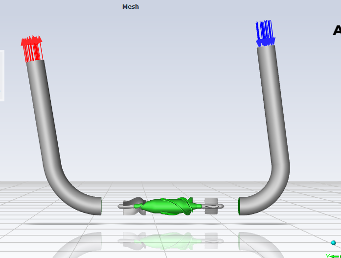
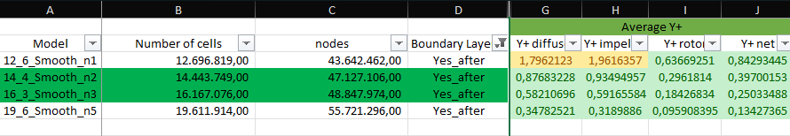
I am using Poly-Hexcore meshes. The simulations are currently being run with the ~14.4 million cells mesh. The average y-plus is very close to 1 (depending on the mesh level it ranges roughly from about 0.3 up to about 1.8), and on the impeller surfaces it is also around this range. However, I currently only have 3 prism layers in the boundary layer. I understand this is not ideal for the SST model and could affect near-wall resolution and separation prediction. I can increase the number of prism layers (e.g., 10 or more) and adjust the growth rate and total thickness accordingly. But independently of the mesh always the pump works as a turbine.Operating point:
The operating conditions (rotational speed and flow rate) are taken directly from the pump supplier performance curves and are very similar to my experimental data. For this reason, I do not believe I am imposing an unrealistic mass flow for the given rpm. That said, I will still run a sweep of mass flow rates around the nominal point to check whether the current condition lies near stall or another unstable region.Pressure monitoring:
I am monitoring pressure both at the pump outlet and at planes located at the end of the inlet and outlet pipes (further upstream and downstream). I will also set up report definitions for total pressure sufficiently far from the rotor and evaluate the total pressure ratio to avoid contamination from wakes and recirculation.Main issue:
The main issue remains that the pump is not generating pressure (negative dp), effectively behaving like a turbine. Since I have successfully simulated other pumps using the same Fluent settings and workflow, I am not sure whether this behavior is primarily related to the mesh (e.g., boundary layer resolution) or to some other aspect of the setup specific to this geometry or MRF configuration.Next steps:
I will rerun the simulation with an increased number of prism layers and re-check total pressure rise, torque sign, and flow field. I can share torque values, total pressure ratio plots, and velocity/flow angle distributions if that helps further diagnose the issue.
-
- You must be logged in to reply to this topic.
-
5289
-
1885
-
1403
-
1267
-
1021
© 2026 Copyright ANSYS, Inc. All rights reserved.
