Preprocessing

Preprocessing

Topics related to geometry, meshing, and CAD.

Ansys fluent

    • toullouselebron
      Subscriber
      Oh my God. I have been trying to get Ansys to create the mixing elbow mech because my computer, for some reason, doesn't allow me to import the mesh that is on the class website; so I am now building it, God save my soul; and I got it to a point where I have 2parts, to bodies, even though I did everything that the "tutorial" said to do. I need to turn the cold inlet small pipe (40mm diameter) and the large mixing elbow (100mm diameter) into 1 part, 1 body. Please help me! The "tutorials" that I found on the Internet are quite old, and I'm wondering if they're out-of-date.
    • toullouselebron
      Subscriber

      I know that the extrusion should not go above the elbow's face to work as one body, so I tried to extrude the half-cylinder to the surface of the elbow, unlike the first try, but I don't know how to cut a hole in the elbow, so I'm S.O.L. again. This is the first time I'm working with this God-forsaken program, and I've never been more frustrated with a software package in my life. The above quote has a mistake. It's a 25mm diameter pipe, not 40mm, the cold-inlet stream.

    • peteroznewman
      Subscriber

      Hello toullouselebron,


      Any piece of software with advanced capabilities is going to be difficult for a new student to learn. Yes, it's going to be frustrating, but there are plenty of people here who can help. Are you skilled at any CAD system?  You can use that and export the solid that represents the fluid into ANSYS instead of trying to learn DesignModeler or SpaceClaim.


      Which release of ANSYS are you using: 18.2, 19.2 etc?
      Which CAD system are you good at?
      If you have no CAD, which ANSYS Geometry editor do you want to use: DesignModeler or SpaceClaim? If you have no idea, you should start learning SpaceClaim as it is the newer software and is where the developers will focus on improvements.


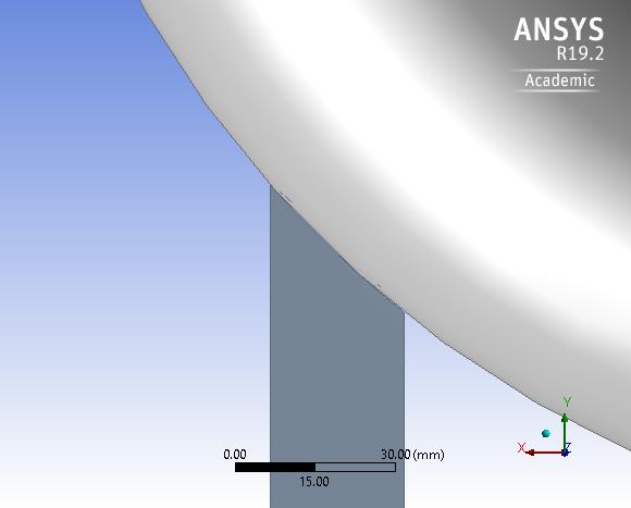
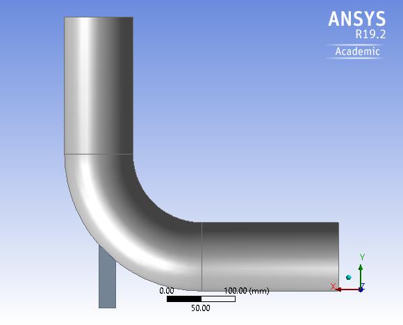
      Please insert an image of the pipe specifications, even if you just sketch it with a pencil on paper and take a picture of that, it will be good enough.  So the inlet is a 25 mm diameter and the outlet is 100 mm diameter. Does it go through a 90 degree bend?  What is the offset of the center of the outlet from the center of the inlet? How long is the straight pipe section from the inlet and the outlet before the elbow begins? I'm sure you can get the geometry you need without too much difficulty.


      Peter

    • toullouselebron
      Subscriber

      Hi.


      The diameter for the large pipe and elbow is 100mm. The diameter of the small pipe is 25mm. The height from the base of the small pipe to the face of the elbow for the part of the elbow that is closer to the ground is 75mm, and the height from the base of the small pipe to the elbow for the part of the elbow that's farther away in the Y direction is 100mm. The height from the bottom of the small pipe to the top in the Y direction is 425mm. 

    • peteroznewman
      Subscriber

      Looks good.  Did you use DesignModeler? If so, to change two overlapping bodies into one, you use Create, Boolean, which comes up with Unite as a default and select both bodies and click Generate. You will have one body!  That would be all you need to do if the small pipe was connected to the large pipe at a hole in the large pipe and you were modeling the fluid bodies.


      But reading your description more closely, I see that maybe the small pipe is inserted for some distance (425 mm) into the center of the large pipe. That is a bit more difficult. In that case, you want to model the pipe wall thickness of each pipe. You can construct concentric circles on the cross-section sketch for each pipe. After the Boolean, you need to use Tools, Fill to create the Fluid Body. 


      Peter

    • toullouselebron
      Subscriber

       I tried to upload the tutorial pdfs, but they're too large. The last part, the last two pictures, were not part of the "tutorials." They're things that I tried on my own.


    • peteroznewman
      Subscriber

      Put the pdfs in a zip file. If the zip file is < 120 MB, you can Attach it to your post above. Also, reread my post above as I edited it.


      Will you be using SpaceClaim?

    • toullouselebron
      Subscriber

      This link is very similar to the pdfs I have:


      http://www.southampton.ac.uk/~nwb/lectures/2011/CompressibleFlowLab/flu_tg%5B1%5D.pdf


      The main difference is that this one is in inches, and if you directly translate it to the one I was using, you'd have to assume that each inch is 2.5 cm instead of 2.54cm, so instead of 2 inches being 50.8mm it would just be 50.

    • peteroznewman
      Subscriber

      Will you be using SpaceClaim or another CAD system?


      In the pdf Example 1.1, the small pipe just enters at a hole in the large pipe, so the first paragraph in my previous post applies, just do a Boolean Unite of the two fluid bodies.

    • toullouselebron
      Subscriber

      well, that and the fact that they start the problem off in meters, and then go through the tutorial in inches, for whatever reason.

    • toullouselebron
      Subscriber

      I don't know what those are. Space what? I shouldn't even have to do this. The homework assignment came with the mesh file, but for some reason, I can't see it when I try to import it, so I figured I'd do it myself...now many hours later, I feel like I should have bashed my skull up against a concrete wall for the last 24-30 hours because it might have been more fun.

    • toullouselebron
      Subscriber

      I hadn't refreshed this in a while, so I wasn't ignoring you, just didn't see your posts.

    • toullouselebron
      Subscriber

      I was using designmodeler in Ansys fluent. After this, I need to have a cold inlet and get temperature profiles and such.

    • peteroznewman
      Subscriber

      Example 1.1  Is this what you want to do?


    • toullouselebron
      Subscriber

      By the way, it should just be up to the face. I have a ridiculous amount of Ansys files. The first picture is different than the last two, like I said in the above post, but I figured that it might be confusing if I did it that way. The first picture is different from the last two, so there shouldn't be an extrusion. The extrusion came from the wonderful tutorial that I was using at first. Then I figured out how to bring it up to the just the face of the elbow by myself.

    • toullouselebron
      Subscriber

      Yes, but in mm. The diameters are 100mm, which is close to 4 in, and 25mm, which is close to 1 in. 

    • toullouselebron
      Subscriber

      I think the problem set changes the density of the fluid, but that's not a problem, once I get to the first step of my homework, after I figure this out...hopefully.

    • toullouselebron
      Subscriber

      I'll owe you a beer, or a six pack, or a meal, if you help me out with this. I am going crazzzzzzzzzzzzzy!

    • peteroznewman
      Subscriber

      Follow these directions to make a Workbench Project Archvie .wbpz file of the project that has the good geometry in it. You didn't have to do up to face, you can just overlap the solids then the Boolean Unite takes care of the overlap. Attach that file after you post your reply. Do we will stick with DesignModeler for now.


      Where in the world are you?

    • toullouselebron
      Subscriber


      Above is the inside of the pipe. It's half a pipe, since symmetry can take care of the fluid-flow problem and heat-transfer problem. You can see that it just comes up to the face of the elbow. Below is another inside view, taken at about a 90 deg angle with respect to the above view.


    • toullouselebron
      Subscriber

      I'm in Arizona.

    • toullouselebron
      Subscriber

      Yes. DeignModeler should work, right?

    • peteroznewman
      Subscriber

      Send me the .wbpz Project Archive, as described in my last post, so I can have your geometry.

    • toullouselebron
      Subscriber

      I have a file with the protruding pipe through the elbow. Boolean What? How do I use that? I extruded it, like the paper said, but then in the next part, I crashed and burned like a drunk guy trying to pick up a model in a bar.

    • toullouselebron
      Subscriber

      Should I send you the protruding-pipe one?

    • peteroznewman
      Subscriber

      Do you want to wait while I construct those two bodies, or go File > Archive and save the .wbpz file and Attach that file?

    • peteroznewman
      Subscriber

      Yes, send the one where the small pipe interferes with the large pipe.

    • toullouselebron
      Subscriber

      I'll do the archive. I've annoyed myself up to this point, might as well keep going. Give me a moment.

    • toullouselebron
      Subscriber

      Okay. I have to go eat anyway. I haven't eaten in about 24 hours, and I need to ride my bike to work tomorrow, to go teach a bunch of crazy fool English.

    • toullouselebron
      Subscriber

      crazy fools

    • toullouselebron
      Subscriber

      The first one was wrong. I sent you the wrong file. Attached is the correct file.

    • peteroznewman
      Subscriber

      You need one more line in Sketch1 on Plane4 to create a solid sweep. You don't need a Boolean because the next operation is Add Material.


    • toullouselebron
      Subscriber

      Yes

    • toullouselebron
      Subscriber

      That would be awesome! Thank you.

    • toullouselebron
      Subscriber

      Can I start from the attached file, because I'm sick of starting over?

    • peteroznewman
      Subscriber

      Here is a version that works.

Viewing 35 reply threads
  • The topic ‘Ansys fluent’ is closed to new replies.