TAGGED: ansys-circuit, error, transient
-
-
January 23, 2024 at 8:41 am
wen bo
SubscriberHi,
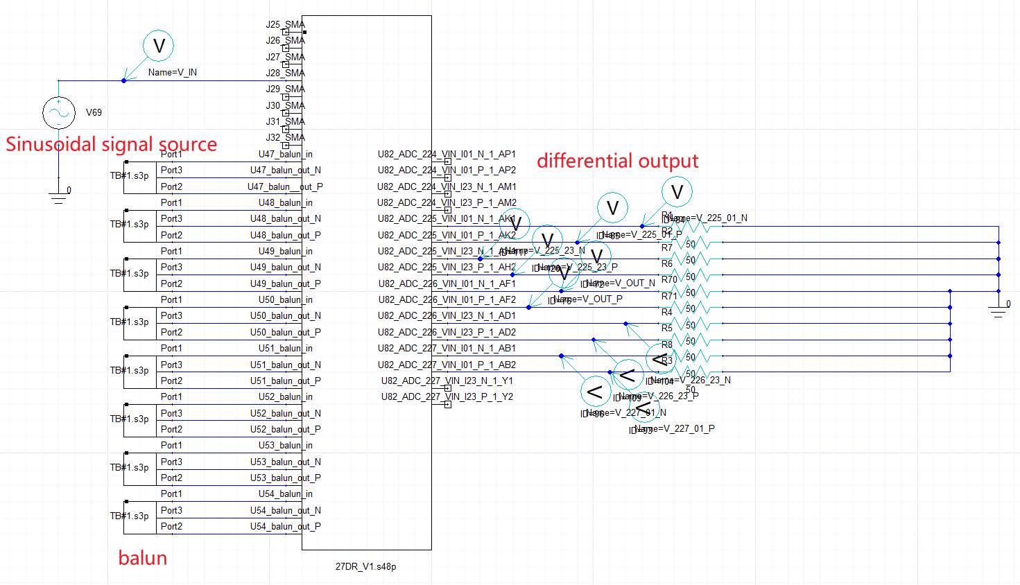
I am doing the simulation of crosstalk/isolation between channels. I have finished the simulation analysis of LNA, and now I want to observe the magnitude of crosstalk in the time domain and I run into a problem.Below is the schematic diagram:
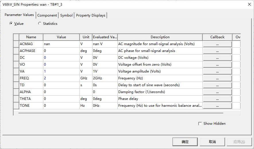
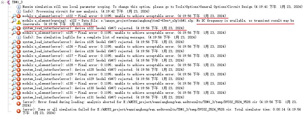
As shown in the figure, the frequency of the sinusoidal signal source is set to 2GHz, and the balun converts the single-ended input signal to the differential signal output.Then I added transient analysis for simulation and reported the following error:
So, why do I simulate a 2GHz waveform and the simulation shows a warning that the S-parameter model has no DC frequency?
Also, what is the cause of the error in the figure for device s125(model tb#7) rejected, and is it caused by the above warning?
Then I want to use sine wave simulation output waveform, encounter this kind of problem how to solve?
Thank you.
-
January 25, 2024 at 5:24 pm
Tony Donisi
Ansys Employee-
January 26, 2024 at 2:59 pm
Dan Dv
Ansys EmployeeThe s-parameter rejection is due to the state-space (the method by which we solve s-parameters in the time domain) fitting error is greater than 10%. That is a very strong indicator that the model is behaving in a non-physical manner. I would recommend running the causality checker in the Network Data Explorer to see if if flaggs the model as non-causal.
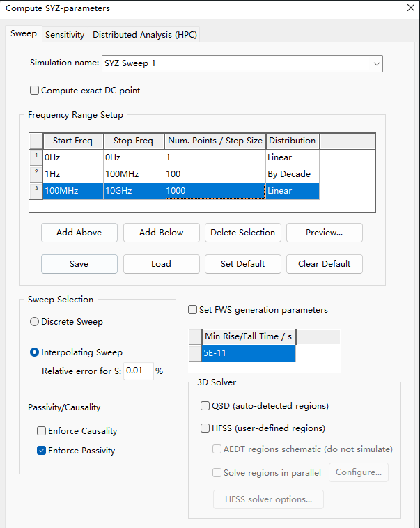
Though you had mentioned this being based on an LNA simulation. Undersampeld frequency domain data can often appear as numerically non-causal. On a related note, the no DC point warning is coming from the same s-parameter model. What was the frequency sweep settings for the LNA that crated this?
-
January 26, 2024 at 3:20 pm
wen bo
SubscriberThank you for your answer.
I've done the frequency domain scan of this network, no problem. Now I want to input sinusoidal signals at the 8 SMA inputs to observe the amplitude-phase consistency of the 8 channels' differential output waveforms, so I need to observe the results in the time domain.So I added transient analysis.
However, the error reported in the problem (model tb#7) is the S-parameter model(balun) that I downloaded from the official website of the manufacturer, and there is no DC data in it. The model itself I checked for causality and there was no problem.
Now, how can I do what I said above about looking at the results in the time domain?
-
January 26, 2024 at 3:26 pm
Dan Dv
Ansys EmployeeI really can't say without seeing the model in question. You said it came from a vendor's website. Would you be able to share that link here?
-
January 28, 2024 at 7:57 am
wen bo
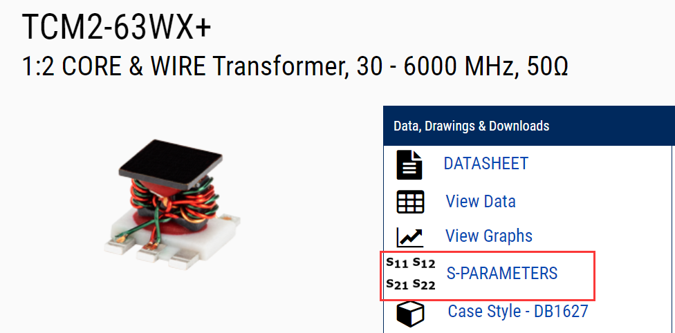
SubscriberThe balun is TCM2-63WX+, and the link is:1:2 CORE & WIRE Transformer, 30 - 6000 MHz, 50Ω | TCM2-63WX+ | Mini-Circuits (minicircuits.com)
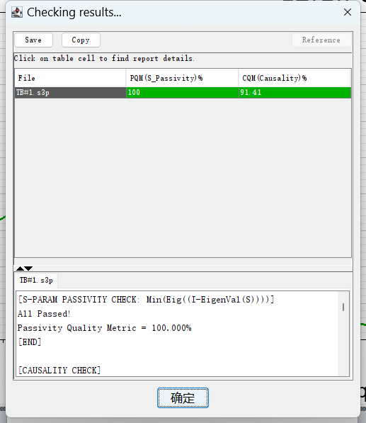
The following figure shows the results of balun's S-parameter check.
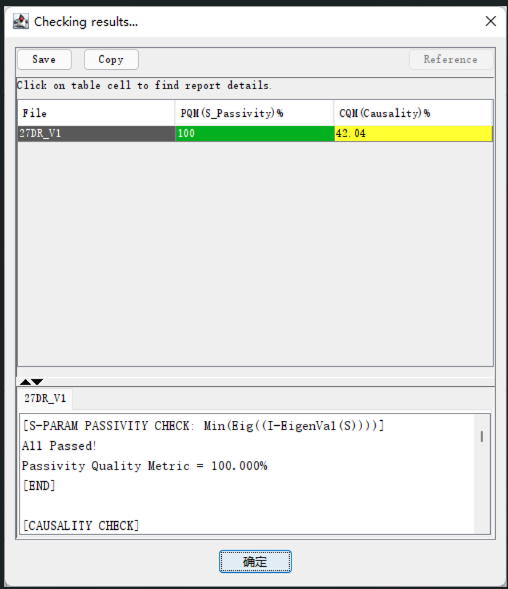
In addition, the S-parameter model of PCB was extracted by SIWAVE, and I checked its causality and found that it was not good. Does this have any impact on the error (device s125(this is a balun model, not a PCB model) tb#7 rejected) in transient simulation?The following figure is the causality check result of the S-parameter model of PCB.
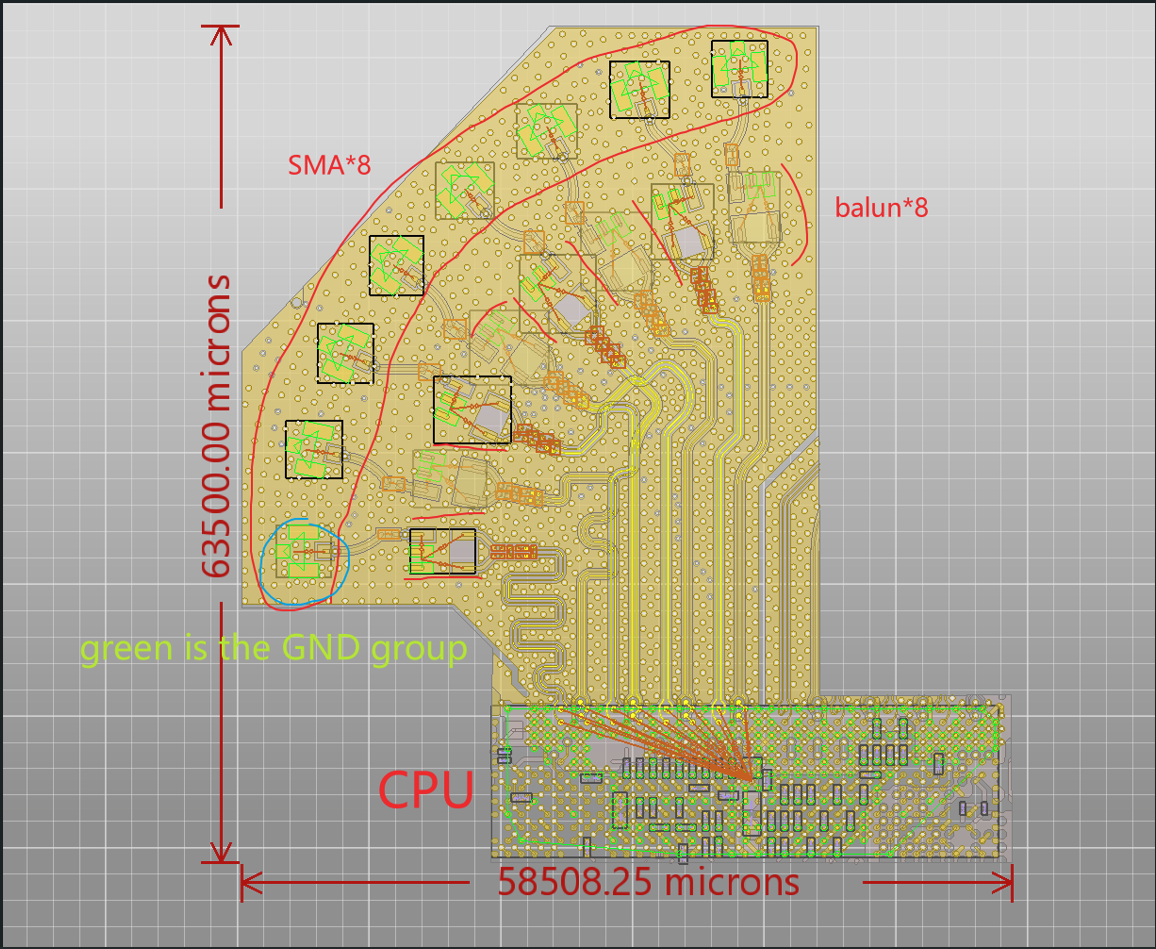
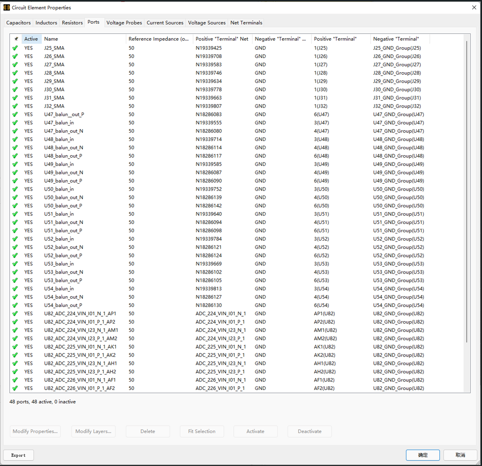
And the following is the model and simulation Settings of PCB in SIWAVE, why the causality of PCB's S-parameter is so poor? Is there any way to improve it?
-
January 29, 2024 at 6:30 pm
Dan Dv
Ansys EmployeeI looked at the balun model. Using the Network Data Explorer I see that the model is passive, but definately not causal. Really, that issue shoud be on the vendor to fix by providing a better set of s-parameters. Alternitavely, you can change the options for the s-parameter model in the schematic to use Convolution (right mouse click on the component, select edit model, then in the optoins tab change the method from state-space to covolution).
Convolution will not reject models for being non-physical, but it is a far less robust algorithm than state-space. But in leiu of a proper model from the vendor, it may be the best path forward.
As to your question, I don't think any potential issues with the SIwave model should impact the error that the balun is causing.
Best regards,
-Dan
-
January 30, 2024 at 1:15 am
wen bo
SubscriberThank you for your help.
-
-
-
January 25, 2024 at 5:27 pm
Tony Donisi
Ansys EmployeeAny time a transient analysis is done, a DC point is needed. The transient engine starts with the DC point and steps from there. If you want to just see a linear frequency domain analysis just us the AC analysis by setting the AC voltage in the source and looking at the linear output voltage.
-
January 26, 2024 at 6:47 am
-
-
January 26, 2024 at 3:18 pm
Tony Donisi
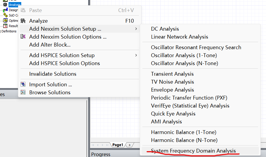
Ansys EmployeeNo, just put in a "Linear Network Analysis" and a source with an ACMAG and an ACphase (located in the sinusoidal source on your schematic and in the propwerties in your screenshot) and you will be able to plot voltages with the linear analysis.
-
January 26, 2024 at 3:22 pm
wen bo
SubscriberI Get It.Thank you for your help.
-
-
- The topic ‘ANSYS Electronics Circuit:Transient analysis error’ is closed to new replies.


-
4828
-
1587
-
1386
-
1242
-
1021

© 2026 Copyright ANSYS, Inc. All rights reserved.

