TAGGED: bending, stress-strain
-
-
September 1, 2021 at 9:16 am
Shuo1
SubscriberDear Ansys users,
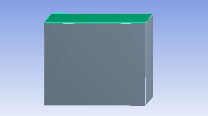
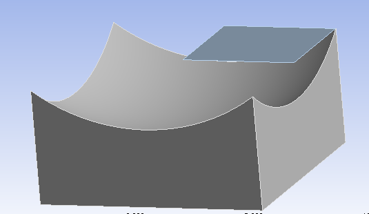
Hi. I'm recently simulating a bending process of a very thin silicon thin film into a spherical geometry. I have a glass holder with a concave cavity (with a specific curvature radius) on which the silicon thin film is placed, and a silicon thin film on top of the holder as shown in the image below. I would like to apply a force, a pressure or a displacement on the thin film. Then I would like to analyse the strain on the thin film after the deformation.
I've tried several setting up but they didn't work. I'm planning to use a 1/4 symetric module for the simulation. Could someone please let me how I can achieve the deformation into a perfect spherical geometry for the thin films? I really appreciate it. Many thanks in advance!
Kind regards,
Shuo
September 1, 2021 at 10:21 ampeteroznewman
SubscriberPlease give details on the how you set up the model and the error when your model "didn't work".
Another member recently had a similar model. /forum/discussion/comment/119244#Comment_119244
Read that discussion and come back with questions.
September 1, 2021 at 10:47 amSubscriberHi, thank you so much for your reply. I have read through the case from another member. It's quite similar but I don't have a roller on the top of the thin film to form a spherical form.
First, I set up a solid model (flexible) for the thin film and a solid model (rigid) for the holder. When I give four fixed support at the vertices of the thin film and fixed support at the bottom of the holder, with pressure on the top of the thin film, the film got stuck in the holder as shown below if the pressure is large. It seems the holder didn't play like a rigid solid.
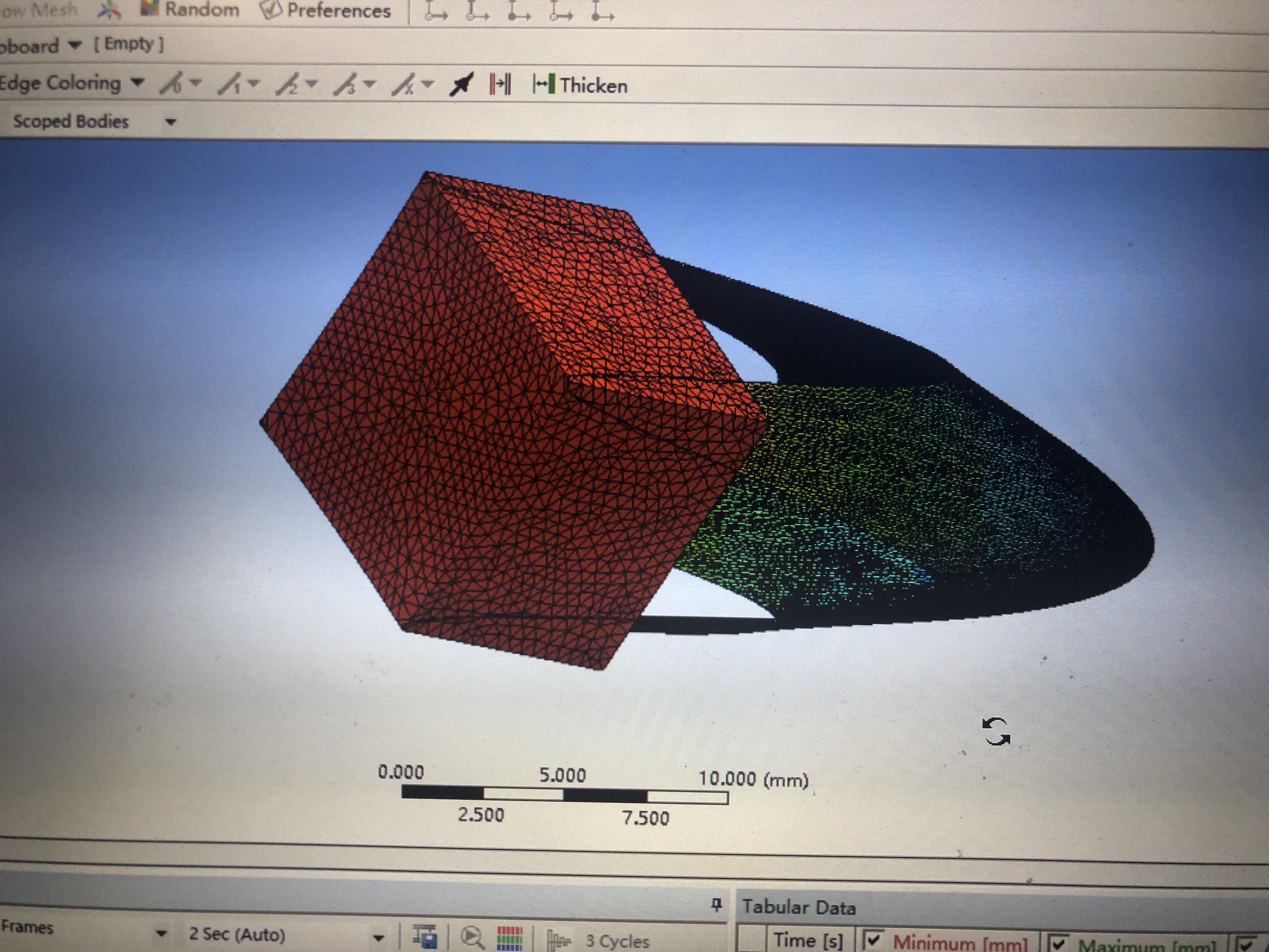
Then I gave proper pressure to make sure that the film is out of the holder. But I realized I should not give fixed supports at the vertices of the thin film which will cause big stress at those vertices. I tried to use displacement functions but I don't know how it should be set so I can obtain a perfect spherical geometry for the thin film as shown in the image below (from papers).
Please forgive me if my question is silly because I'm new to ANSYS. I only learned to use ANSYS for a week. Any help is very appreciated. Thanks a lot! Regards, Shuo
September 1, 2021 at 10:59 amSubscriber1) consider using shell elements on a surface to represent the thin film. This will be more accurate and efficient for bending.
2) consider setting the holder solid body to be a Rigid body, not flexible. This will reduce the solution time.
3) cut the model into 1/4 of the domain in the geometry editor.
4) Use a Fixed Joint to Ground on the holder to provide the necessary support.
5) Apply Symmetry Boundary Conditions on the two cut edges of the surface that represents the thin film. On a shell element, that means zero displacement along the axis normal to the cut plane and zero rotation about the two orthogonal axes. There is no need to hold the corner of the thin film. It will be free to slide along the surface contact defined in #6.
6) Add Frictional Contact between the thin film surface and the holder face.
7) Under Analysis Settings, turn on Large Deflection, turn on Auto Time Stepping, set the Initial and Maximum Substeps to 100.
September 1, 2021 at 3:23 pmSubscriberThank you so much for your suggestions which I really appreciate. I will try to do the simulation considering these helpful suggestions.
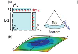
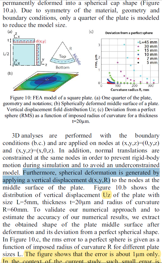
Alternatively, I'm wondering if the spherical geometry deformation can be realized by using only the displacement function without the holder at the bottom of the thin film, which is demonstrated in a paper as shown below. I think it's easier compared with the deformation with the holder. Could you please have a look and kindly let me know how it is realized? I'm so confused about "spherical deformation is generated by applying a vertical displacement d(x,y,R)" where R is the curvature radius. Many thanks in advance for your patient guidance.
With kind regards Shuo
September 1, 2021 at 11:32 pmSubscriberIt may be possible to apply a deformation to a set of nodes in the form of a spherical surface, but that seems artificial. Using pressure to press the film down onto a rigid spherical surface seems realistic.
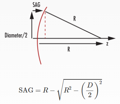
To deform a flat surface into a spherical surface, create a cylindrical coordinate system at the center of the film, where the XY axes are in the plane and the Z axis is normal to the plane. Create a deformation as a function of the X coordinate, which is the radial coordinate, r.
A spherical surface is defined by the Radius of Curvature R and the radius D/2. I would replace D/2 with r in the equation below because if you have the r,theta,z coordinates of a node in the coordinate frame described above, then the value of r is the X coordinate value, and the Z coordinate is calculated by the SAG equation.
 September 2, 2021 at 8:58 amSubscriberHi. For the deformation by applying pressure on top of the thin film, I've tried last night. I gave fixed support to the top surface of the concave holder, it turns out the pressure will affect the strain and stress of the thin film especially at the corners (very big) because you need to make sure the centre of thin films must be in contact with the holder for spherical deformation. But at that time, the pressure for the thin film around is too much.
Thanks for the suggestion by using a displacement function and I think it's really a good one! I've created a cylindrical coordinate system at the centre of the thin film as shown below. Displacement and Displacement 2 are for the symmetric boundary conditions of the 1/4 thin film. Displacement 3 is for the deformation of spherical geometry from the bottom side of the thin film. Then I selected the cylindrical coordinate system that I've created (Fig 1). When I give Z component a function of x, the cylindrical coordinate system will change to the original one (Fig 2). From the results, I can see the deformation is only from x-axis which I believe it's because the cylindrical coordinate system was changed (Fig 3). But I don't know how to solve this problem. Could you please let me know where I was doing wrong and how I can prevent the cylindrical coordinate system from changing to the original one. Many thanks in advance!
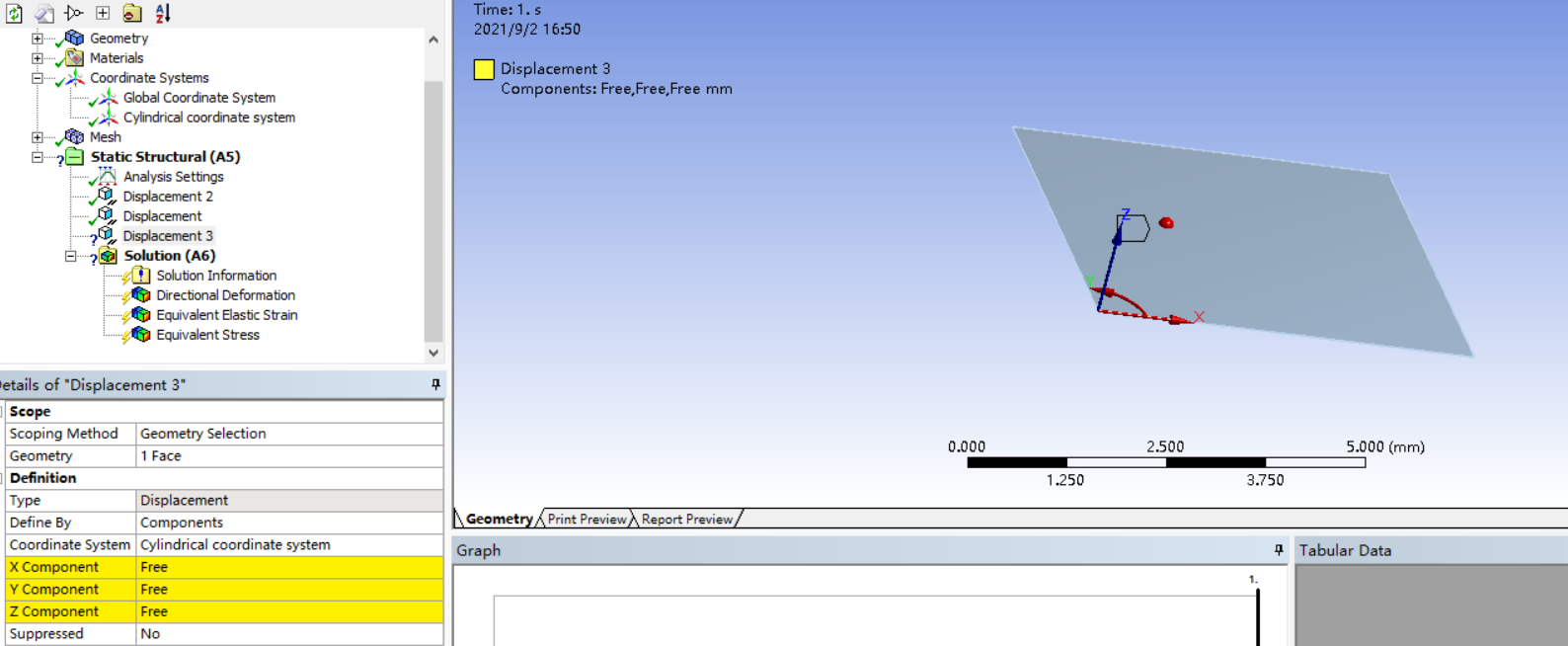 Fig 1
Fig 1
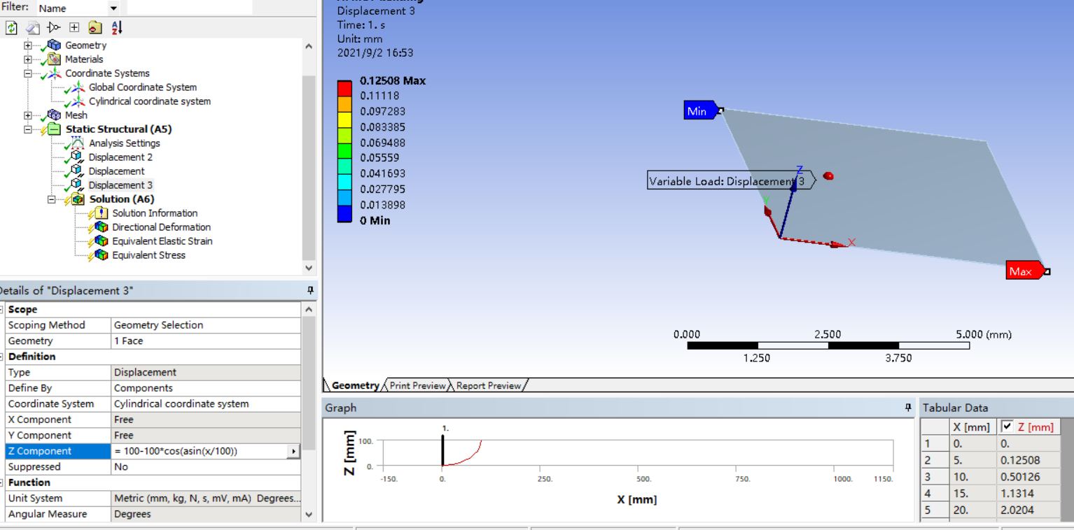 Fig2
Fig2
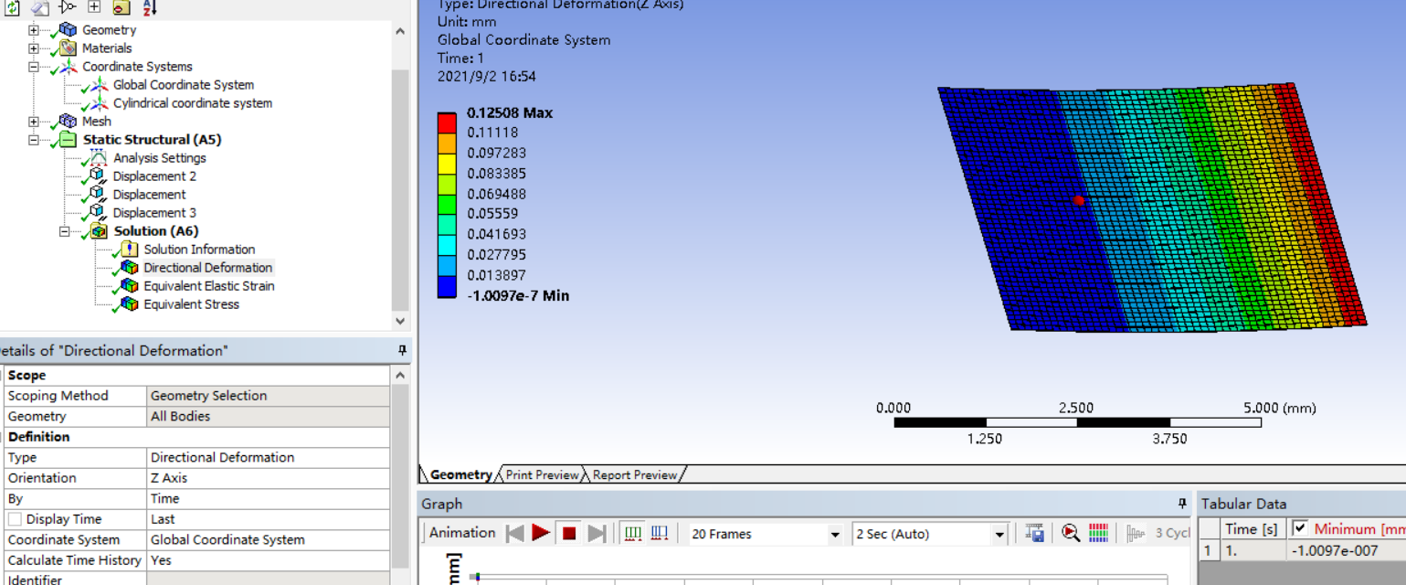 Fig3
Fig3
Thank you so much again!
Regards Shuo
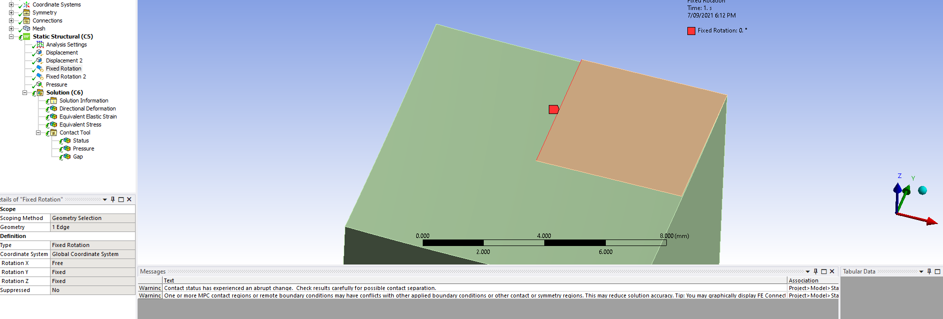
September 2, 2021 at 10:45 amSubscriberIn Figure 1, you have not completed all the supports required for two planes of symmetry on a Shell model. You haven't applied the Fixed Rotations. There needs to be one for each plane. The image below shows the Fixed Rotation for the edge that has the Y=0 displacement. The second fixed rotation on the edge that has the X = 0 displacement has Rotation about X Free and the other two Fixed.
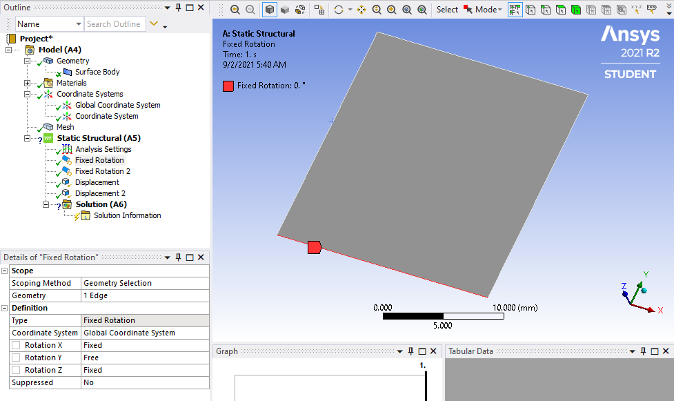 So you have found the pressure causes higher stress and strain the further out from the center you go. That is to be expected. Rerun it with the added rotational supports.
When I said it may be possible, that is because I was not sure and didn't try it myself first. When I am sure, I say you can do something. I tried out what I suggested and you can't achieve what you want using the method I suggested. If it worked, Figure 3 would show circular rings of displacement. The reason it doesn't work is because the Cylindrical Coordinate System is not used to define the location of the nodes, only their displacement. The location of the nodes is in the Rectangular Coordinate System. Therefore the X coordinate doesn't mean a radial coordinate, it just means X so the SAG equation would need both X and Y in the equation to compute the actual radius r, but you can't make Tabular Data a function of two inputs, X and Y using the Workbench interface.
There may be a way to do this using some APDL code, I don't know. There may be a way to do this by importing External Data where the SAG equation is computed in a spreadsheet, I don't know.
I still don't know why you would want to artificially assign a deformation. How do you do that in a practical sense? Probably by making contact with rigid surfaces. You could make a cylindrical solid that is smaller than the film so the corners of the film are outside of the diameter, then you will avoid bending on the corner and instead make contact on a circular edge.
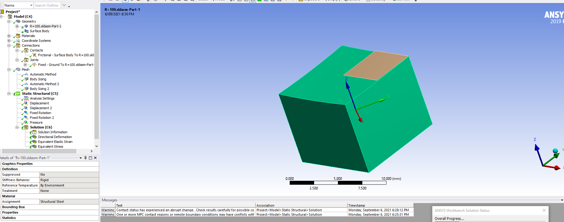
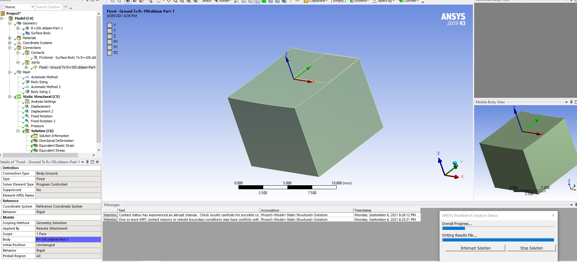
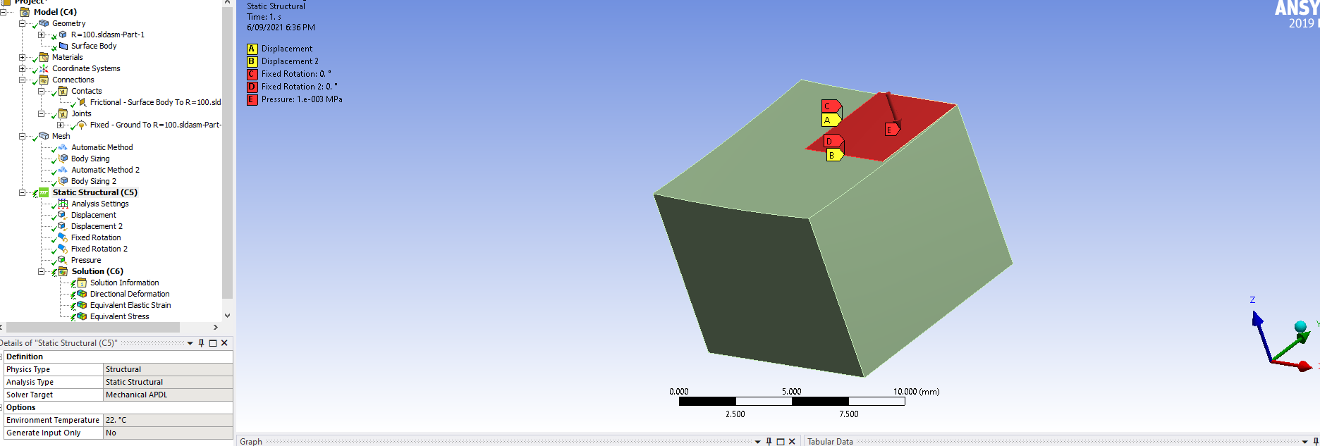
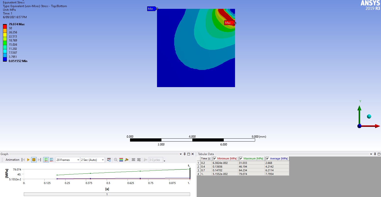
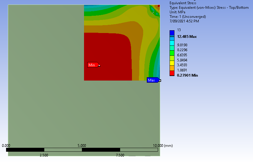
September 6, 2021 at 11:00 amSubscriberHi Peter. Thanks again for the advice. I think what you have suggested makes sense. So I've been working on the simulation by using a holder and pressure on the top of the thin film. But I am still not be able to obtain the desired result. The stress distribution is wired, I'm not sure if it's because the pressure is too large or some reasons else. I think the maximum stress should be at the centres of the edges which is the left-top corner and right-bottom corner. I'm so confused.
My set up for the model has been attached below. Among this, I'm not so sure if the set up for the fixed joint is right. Could you please kindly have a look at the set up and let me know what's happening? I really appreciate it.
Many thanks in advance! Kind regards, Shuo
September 6, 2021 at 3:30 pmSubscriberThis looks like it is working as intended.
For symmetry, on the cut edge that has the X=0 displacement BC, there should be two rotations set to zero, Ry and Rz.
On the cut edge that has the Y=0 displacement BC, there should be two rotations set to zero, Rx and Rz.
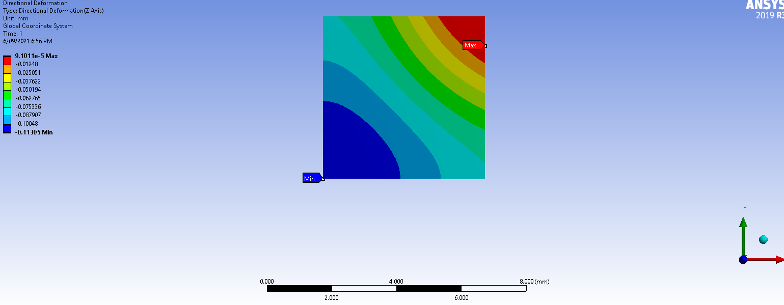
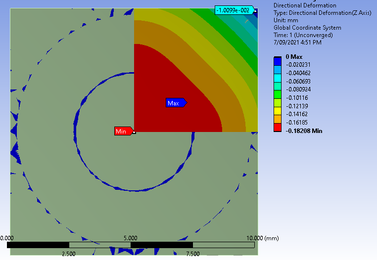
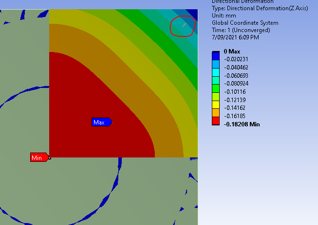
For the plot of Directional Deformation along the Z axis, set the legend to use the Reverse Rainbow color scheme, which will make the largest negative value show as red and the part that didn't move blue.
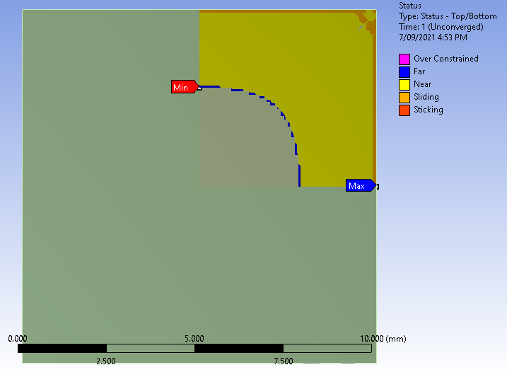
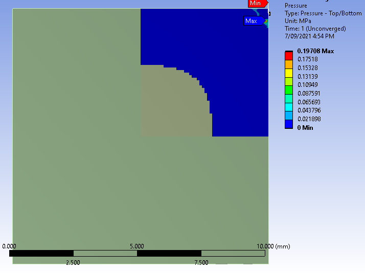
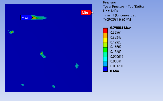
Insert a Contact Tool into the results and insert a pressure plot to see where the silicon chip is touching. You can also insert a Gap plot.
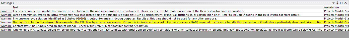
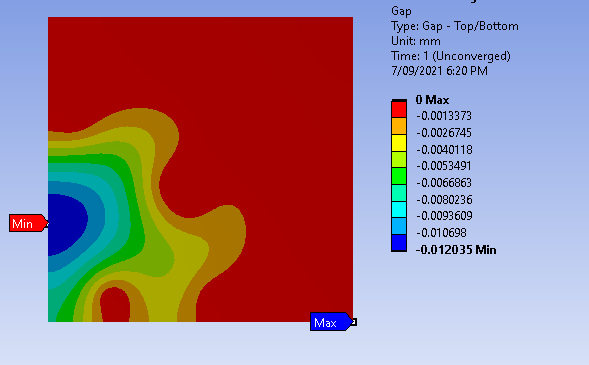
September 7, 2021 at 10:21 amSubscriberHi Peter. Thank you for your suggestions. My simulation results are getting better. But after the simulation, there are red lightning on the solutions which means the simulation is not successful. I have attached some of the simulation results below including the contact tool of status, pressure, and gap. But I don't know what does the result of contact tools mean. Could you please tell me what's happening?
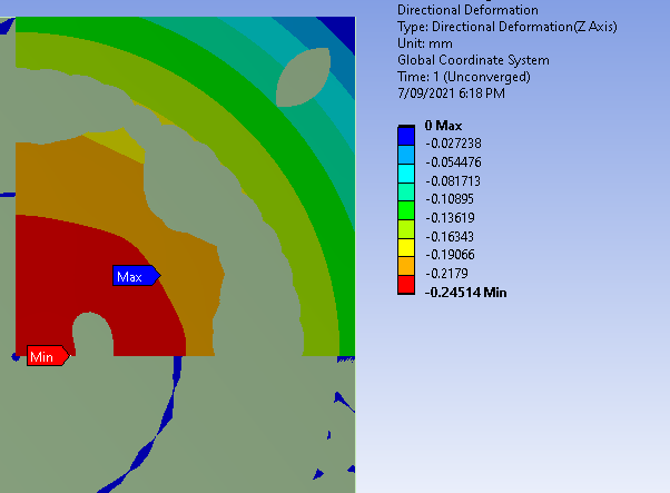
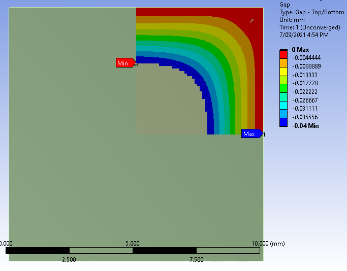 Another issue is that the thin film still penetrates the holder sometimes even if I have already set the holder as rigid. The images below show the penetration of thin films with 0.001MPa (first image) and 0.0005MPa (last three images) pressure. It doesn't make sense that a smaller pressure results in more penetration. I'm so confused.
Any help is appreciated. Many thanks in advance!
Kind regards Shuo
September 7, 2021 at 11:15 amSubscriberOn the Frictional Contact detail is an item called Pinball Radius, which is a radius from the contact surface to search for a target surface. When it finds that, contact elements are created to use in the solution. It is set to Program Controlled by default. What may be happening is that the default Pinball Radius is too small and there are no contact elements at the center of the hollow. The evidence for this is that there is no Gap showing at the center of the hollow. The corrective action is to manually type in a larger number, such as 5 mm.
September 7, 2021 at 2:31 pmSubscriberThanks for the suggestion. I've changed the Pinball Radius and increased the pressure given to the thin film. Regarding the simulation result of the gap in contact tool as shown in Figure 1, it shows no gap between the thin film and the holder, which means the thin film has been attached to the holder. Am I understanding right? If so, regarding the simulation result of the directional deformation as shown in Figure 2, there are still some penetration apparently, but the stress distribution looks fine after I hide the holder. I'm wondering if it is okay? In another word, can I say it is a successful simulation? Any suggestion is helpful and appreciated. Thanks a lot! Kind regards, Shuo
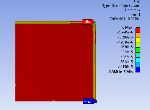 Figure 1
 Figure 2
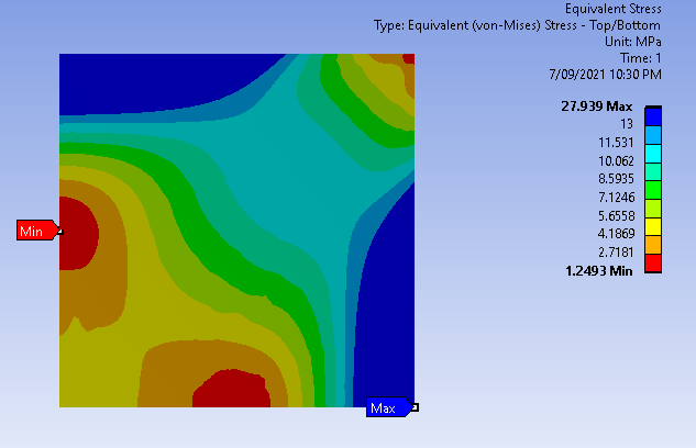
September 7, 2021 at 6:45 pmSubscriberYes, this is a successful simulation.
Change the Stress Legend from Reverse Rainbow back to the Rainbow so the high stress is red and the low stress is blue.
September 8, 2021 at 10:19 amSubscriberHi Peter. Thank you for your reply. I really appreciate all of your help.
(1) Because I'm using the shell element for the simulation of the thin film, I'm wondering if it is shell 181 or shell 281 by default. I can't find what type of shell element that I'm using. (2) The other question is that I tried to export the stress distribution data of all the elements for example to an excel file or a text file. I'm wondering if it's possible to realize in ANSYS.
Many thanks in advance!
With kind regards Shuo
September 9, 2021 at 12:33 amSubscriberYou can change the Mesh Element Order to Linear and it will be Shell 181 or Quadratic and it will be 281. With Program Controlled, you can click on the Solution Information folder and ask to see the Solution Output. In that text file, it will write out the element summary where you can see if you got 181 or 281.
You can right click on a result and Export the data to use in Excel.
September 9, 2021 at 1:39 pmSubscriberThanks Peter, it is really helpful and I'm really grateful for your patient answering.
Today when I tried to apply aninstropy elasticity to the silicon material (I've been using instropy in the previous simulation), I found the simulation result (e.g. stress distribution) by using shell element 281 is smoother than shell element 181. I've checked the definition of these two element, but I'm not sure how these two shell elements have to do with the simulation result. So I'm wondering if shell element 281 is preferred one than 181? Or does that mean shell element 281 is better than shell element 181 when we deal with the aninstropic material?
Many thanks in advance!
Regards Shuo
September 9, 2021 at 7:29 pmSubscriberOn the same mesh, shell281 is a quadratic element, which means it has midside nodes added so there are nearly twice as many points being digitized on the surface and the element can have curved edges and the stress can have a parabolic distribution across the element so it is way better than a shell181 for the same mesh.
Regards Peter
September 14, 2021 at 8:55 amSubscriberHi Peter. Thanks so much for your answer.
Sorry to interrupt you again. When I was doing the simulation, I realized I'll get different solutions when the "Auto Time Stepping" setting in Step Controls is different. For example, if I set it to be Program Controlled, when 5kPa pressure is applied to the thin film, the solution is converged. But if I set it to be on with initial and maximum substeps to be 10, the same 5kPa pressure is applied to the thin film, the solution is un-converged. The same pressure contributes to the different solutions when the Step Controls setting is different. I'm really confused about the difference that Step Controls has played in the simulation. I'm wondering which kind of setting is more closed to the bending of the silicon die in the real world. I really appreciate it if you could help me out with this. Many thanks in advance!
Kind regards Shuo
September 14, 2021 at 10:22 amSubscriberAuto Time Stepping is generally helpful in obtaining a converged solution in a small number of iterations. You have control to override the Program Controlled settings. That means you can get a worse outcome or a better outcome. When I change it to On, it is generally because I have seen the Force Convergence Plot under the Solution Information folder and I know that more substeps are going to be helpful. Instead of 10 substeps, try 100 initial and minimum substeps.
If the solution converges, it doesn't matter if it got there in 15 iterations or 150 iterations. The result has the same quality, but you will wait 10 times longer for 150 iterations than 15.
September 15, 2021 at 2:19 pmSubscriberHi Peter. Thanks for your answer. Yeah setting the Initial and Maximum Substeps to 100 truly cost me much more time. Does that mean I don't need to set the Auto Time Stepping to be on if I can get a convergence plot with Program Controlled because the results always have the same quality? I've tried but it seems like it's very hard to get a convergence plot when I set 10 initial and maximum substeps. Instead, it's easier to get a convergence plot when I set the Auto Time Stepping to be Program Controlled Please let me know if I understand it wrong. I really appreciate it. Many thanks! Shuo
September 15, 2021 at 9:56 pmSubscriberIf Program Controlled is working, that is a good setting.
September 19, 2021 at 12:57 pmSubscriberHi, Peter.
Sorry for interrupting you again. I got some problems when I tried to curve a thin film on a concave holder with radius of curvature of 10mm as shown below. I used the exact same setting for all the simulations. The same setting works for other simulations with larger radius of curvature for the holder (e.g. 50mm, 100mm). I've tried everything I can do but it's still not working. The error is shown as below. Sometimes it shows "An internal solution magnitude limited was exceeded". I've checked the solution information but I'm still confused. Is it because the radius of curvature is too small for the simulation?
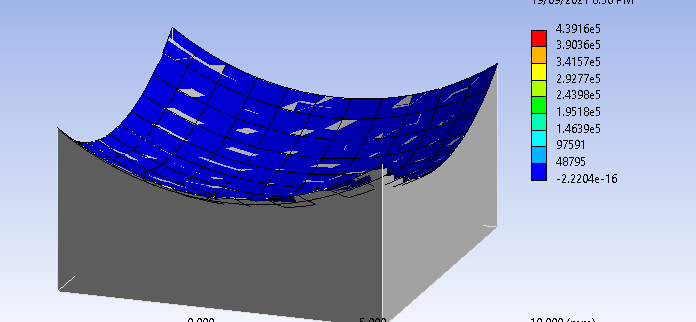
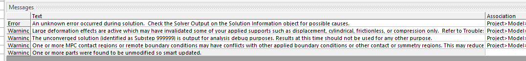
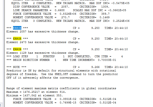
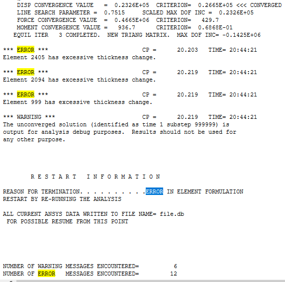
Could you please have a look and let me know what is happening? Many thanks in advance. I really appreciate any help.
Kind regards Shuo
September 19, 2021 at 4:42 pmSubscriberThe mitigation for an excessive thickness change error is to force the solver to take smaller steps so the change is not excessive.
Under Analysis Setting, Auto Time Stepping = On, set the Initial and Minimum Substeps to 100 (or 4 times bigger than the current minimum).
September 20, 2021 at 3:02 amSubscriber
Viewing 24 reply threads- The topic ‘Ansys 19.2 simulation of bending a silicon thin film into a spherical geometry’ is closed to new replies.
Innovation Space Trending discussions
 Top Contributors
-
peteroznewman
 5954
5954 -
scabo
 1906
1906 -
Dennis Chen
 1420
1420 -
javat33489
 1307
1307 -
Shyam Prasad V Atri
1021
Top Rated Tags
© 2026 Copyright ANSYS, Inc. All rights reserved.
Ansys does not support the usage of unauthorized Ansys software. Please visit www.ansys.com to obtain an official distribution.
-