General Mechanical

General Mechanical

Topics related to Mechanical Enterprise, Motion, Additive Print and more.

    • Sanjay1993
      Subscriber

      I am working on a problem in Ansys r19 version and having an error - An unknown error occurred during solution.  Check the Solver Output on the Solution Information object for possible causes. Can anyone help me with this ?


    • peteroznewman
      Subscriber

      This site has 251 results in a Google search of the term "unknown error".  Please read many of them and try at least three things you find in those discussions, then come back with a followup question.

    • Sanjay1993
      Subscriber

      I have looked into the various solution for the error that i got, but it didn't help my work. I am certain that there is some other issue such as maybe in setting up the boundary condition or in my contact elements. Also the deformed part is appearing inside my tool of displacement. Please help me with this. 


      This maybe due to not defining proper contact element, is my guess although i'm not sure.. can you help me with this. I can attach the load and boundary condition for my geometry if that helps. 

    • peteroznewman
      Subscriber

      I can't tell from the image, are those shell elements on a surface with "Thick Shells and Beams"  display style, or are those solid elements.


      I think they are solid elements so your problem is you have only one solid element through the thickness. Don't do that. Go back to CAD and extract midsuface geometry from the solid bodies and try again by meshing shell elements on a surface.


      If you want to try something on this solid model, then put at least two elements through the thickness (if they are solid elements).


      Finally, for either shell or solid elements, under Analysis Settings, turn on Large Deflection and turn on Auto Time Stepping. Make the Initial Substeps 100.

    • Sanjay1993
      Subscriber

      this is the video I have been following for my sample and geometry...


      link: https://www.youtube.com/watch?v=svE0ZW6QrrY&t=1711s


      I'm not sure about the surface elements they have used... But this is what i have been following

    • Sanjay1993
      Subscriber

      Ok..So this is the new error.. Although the job is somewhat getting done as per my test in lab. The error is: Solver engine was unable to converge on a solution for nonlinear problem as constrained . Please check troubleshooting section of the help System for more information. 


    • Sanjay1993
      Subscriber

      I have the error message and the animated video


      Please let me know how to correct it.


    • Sanjay1993
      Subscriber

      Please help me. Let me know if you need the constraints and Boundary conditions

    • Sanjay1993
      Subscriber

      Can anyone help me with this error? 

    • peteroznewman
      Subscriber

      A Google search on this site for "unable to converge" has 104 results.  Please read them, I expect you will find many things to try.

    • Sanjay1993
      Subscriber

      I have checked on internet and couldn't find any solution for the convergence applicable to my problem. Can you help me with this?

    • Sanjay1993
      Subscriber

      Hi Peteroznewman,


      My  Model right now is working with no errors but the material below the plunger seems to be sinking into the solid. I did check large deflection on and I did give a large pinball radius at contact surfaces. I dont know whether it is due to contact or mesh.  Can you please check. I can send the  Workbench Project Archive .wbpz file if it helps. It would be of great help. 


      Sanjay


    • peteroznewman
      Subscriber

      1. Change the strip from a solid body to a midsurface body.


      2. Change the curved bodies from Flexible to Rigid.


      Those two steps will greatly improve the speed of solving.


      Do you have plasticity defined in the material model?

    • Sanjay1993
      Subscriber

      No Plasticity is used in defining the material model. I have been also working on getting a batch code setup to run it in 2D. Although i don't understand the four variables involved here. Namely R1, R2, FTOLN,FKN. i know that these have to do with contact parameters but specifically struggling to get a grip on this.


      Any ideas?


      Code:


      /COM, Define Element Sets


      *IF,X_D,eq,2,then 


        *IF,X_ET,EQ,183,THEN


          ET,ET_TOWS,plane183 


          !KEYOPT,ET_TOWS,1,2


          KEYOPT,ET_TOWS,3,2


          R,RP_TOWS,g_tw


        *ENDIF


        F_TOLN=g_tt*100 


        ET,ET_CNTC,CONTA172


        R,RP_CNTC,0.25,1.0,1.0,F_TOLN      ! R1,R2,FKN,FTOLN


        ET,ET_CTRG,TARGE169


        R,RP_CTRG,0.25,1.0,1.0,F_TOLN   ! R1,R2,FKN,FTOLN


      *ELSEIF,X_D,3,THEN


        *IF,X_ET,EQ,185,THEN


          ET,ET_TOWS,SOLID185   ! 8 node brick (structural)


          KEYOPT,ET_TOWS,2,0    ! Full Integration


        *ENDIF


      *ENDIF


    • peteroznewman
      Subscriber

      Someone else can answer your question. I avoid code when possible.

    • Sanjay1993
      Subscriber

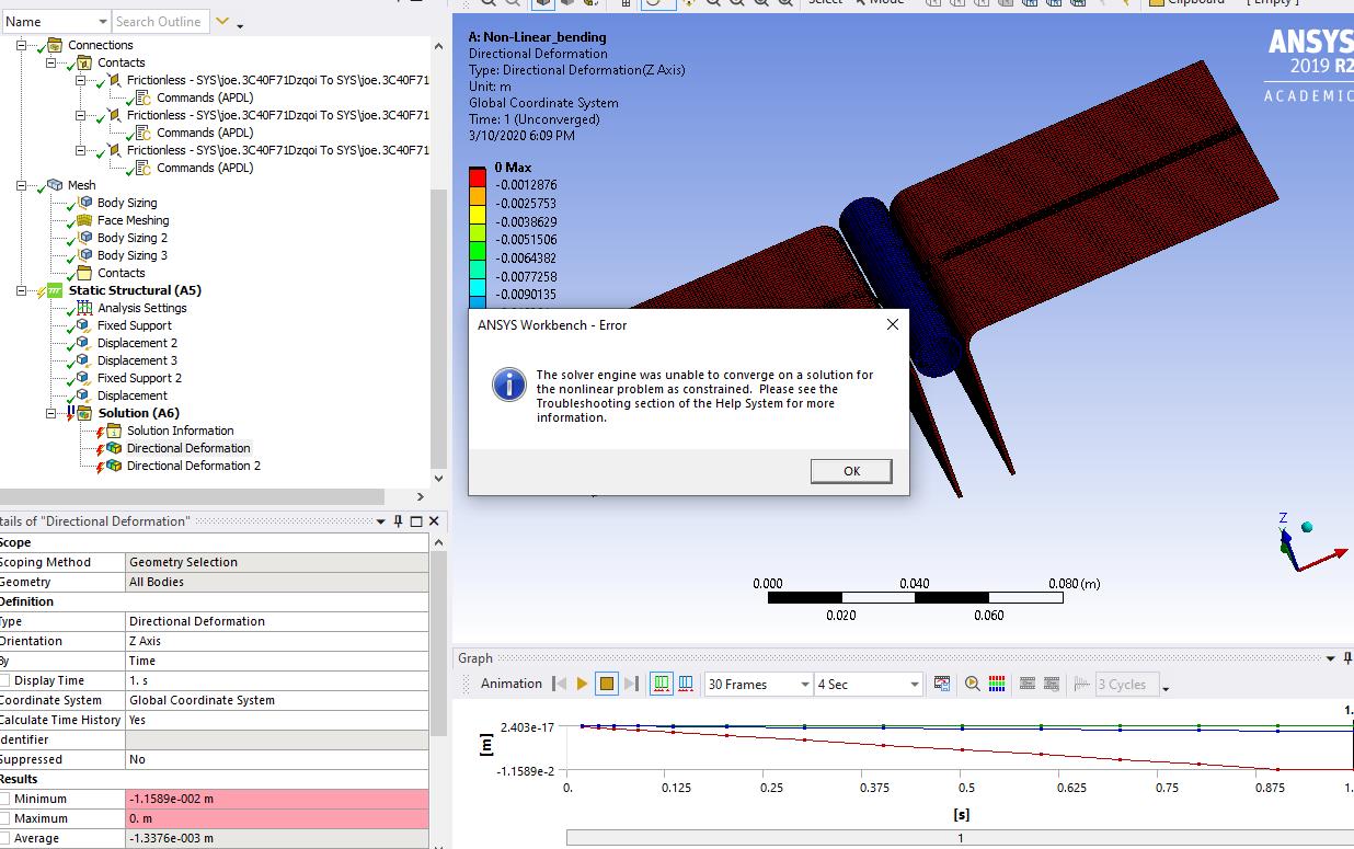
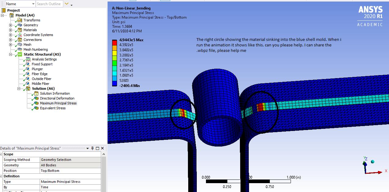
      This is the code that i have for a tow sample placed on a solid mold surface and a plunger deforming it. I need to figure out contacts part so that the tow does not sink into the mold surface as shown in zoomed pic. Can anyone help me with fixing the contact pair surface in order to avoid penetration.


      CODE:


      /clear


      /title, your_ title


      /prep7


      ! Define keypoints and geometry


      k,1,0,0        ! sets a keypoint at (0,0)


      k,2,5,0        ! sets a keypoint at (5,0)


      k,3,15,0       ! sets a keypoint at (15,0)


      k,4,1,1,0


      k,5,1,3,0


      k,6,4,-1,0


      k,7,4,-3,0


      l,1,2,5        ! creates a line with 5 divisions from keypoints 1 to 2


      ! you can remove lines with “ldel”


      l,2,3,10       ! line with 10 divisions from point 2 to 3


      l,4,5,2


      l,6,7,2


      k,8,5,0


      l,1,4,10,,-1,0,0,0,1,0


      l,8,6,10,,1,0,0,0,-1,0


      ! Define Material property and Mesh


      et,1,3         ! sets element type 1 to beam3, the 2d beam element in ANSYS


      mp,ex,1,10e6   ! sets modulus of mtl 1


      mp,prxy,1,0.3  ! sets poissons ratio of mtl 1


      r,1,0.75,0.0625,2.0 ! defines property set 1 for the beam element (A,I,height)


      mat,1          ! sets material to 1, not needed as it defaults to 1


      real,1         ! sets the property set to 1 (this is the default)


      lmesh,1        ! creates a mesh of elements on line1 (undo with lclear)


      lmesh,2        ! creates a mesh of elements on line 2


      mp,ex,2,30e6   ! sets modulus of mtl 2


      mp,prxy,2,0.3  ! sets poissons ratio of mtl 2


      r,2,0.5,0.0417,1.0 ! defines property set 2 for the beam element (A,I,height)


      mat,2          ! sets current material to 2


      real,2


      lmesh,3


      lmesh,4


      lmesh,5


      lmesh,6


      ! COnstraints and Load Condition


      d,7,all,0      ! constrain end


      nsel,s,,,8,16  ! select elements of tow to only translate


      d,all,uy,rotz,,0 ! constrains displacements of elements selected


      nsel,s,,,20,22  ! select elements wall


      nsel,a,,,32,41


      d,all,all,0     ! constrains displacements of elements selected


      nsel,s,,,17,19  ! select elements wall


      nsel,a,,,23,31


      nsel,a,,,1


      d,all,ux,rotz,,0


      f,all,fy,-110.  ! applies a force of 100 units in the (–ve) Y direction


      finish          !exits prep7


      /solu           ! enters the solution phase


      solve           ! runs the solution


      finish          ! exits the solution phase


      /post1          ! enter the postprocessing phase


      pldisp,1        ! plot displacements over original geometry


      finish          ! exits post1, the postprocessor

Viewing 15 reply threads
  • The topic ‘ANsys’ is closed to new replies.