General Mechanical

General Mechanical

Topics related to Mechanical Enterprise, Motion, Additive Print and more.

Analysis Type for Modelling Moving Frame-Like Structure

    • Colleen
      Subscriber

      In the case of a moving frame-like structure, such as a bike, vehicle or wheelchair chassis travelling over a road, what is the appropriate type of analysis to model the fatigue life of the structure? If we model the structure using CAD geometry and describe the input forces using the amplitude based on the profile of the road and the frequency based on the speed of structure, would the fatigue tool and a static structural study be appropriate to analyze the system?

    • peteroznewman
      Subscriber

      Hi Colleen,


      Static Structural with the Fatigue Tool is an efficient way to analyze the fatigue life of a structure. The Fatigue Tool has the ability to use a cycle-history of a load and use the stress from the solution to calculate a life for that structure under that load-history.  This discussion has an example of that. I'm curious how you are going to determine the force on the frame from the profile of the bump in the road.


      One analysis that can be done is a Transient Structural analysis. You can model a single, worst case bump in a road and roll the wheels over that bump. The peak stress can be found during the time simulated and used to look up on the SN curve the number of cycles to fracture of the wheel hitting that bump. You could model a continuously rough road, which which would generate a series of high stress events, and now you have to count how many peaks in the stress were seen and bin the peaks by the different magnitudes since a bigger stress peak accumulates more fatigue damage than a smaller stress peak.


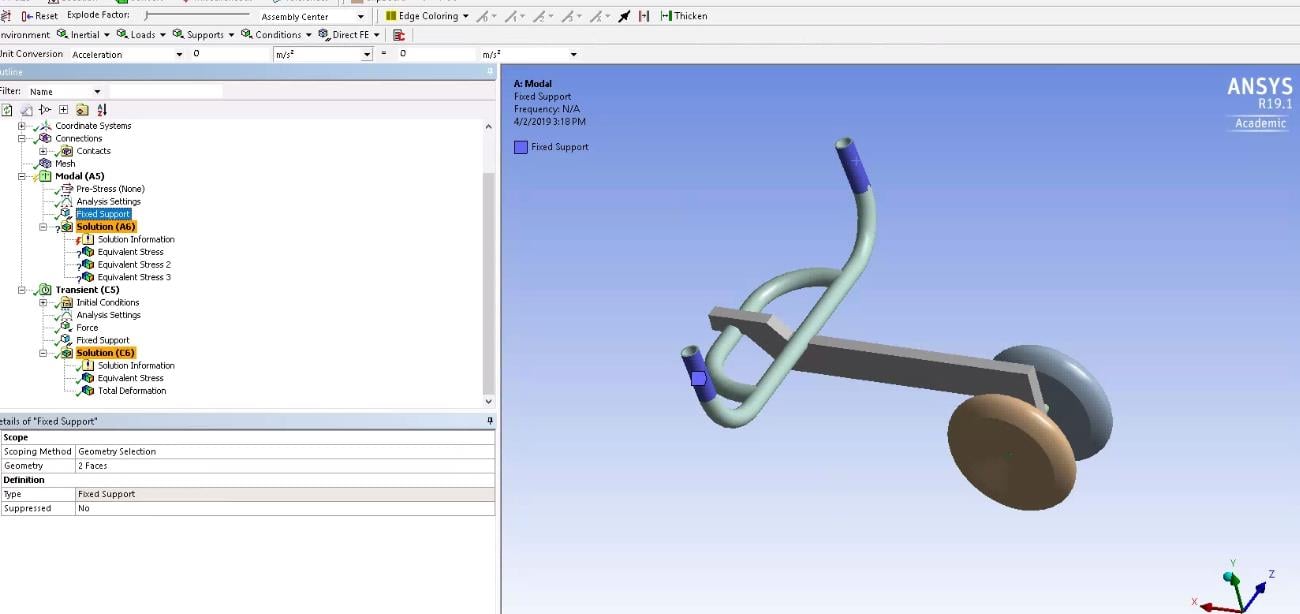
      I have instrumented the frame of a wheeled cart with an accelerometer and driven the cart over bumps in the floor while recording the acceleration-time history. Do you have access to an accelerometer and a data acquisition system?  There is a lot that can be done with this data. Now you don't need to model the road or the wheels. The recorded x,y,z acceleration-time history can be copied out of Excel and pasted into an acceleration-time load on a model. There are linear and nonlinear versions of a Transient Structural analysis. The linear analysis uses a Modal Analysis as a prerequisite and computes in a lot less time, but can't model any nonlinear behavior such as frictional contact. The nonlinear analysis can compute frictional contact during the time history simulation, but takes a lot more time to compute.  The disadvantage to Transient Structural is the huge amount of data generated and the time it takes to compute. The structure has a solution at every time step, and there may be 10,000 time steps/second, so a ten second event will generate 100,000 substeps. That's a lot of data, but it gives an accurate simulation of the peak stress during the event. Then you take that peak stress and look up on the SN curve how many cycles of that event it takes to fracture the material.


      You can take the accelerometer data and convert it into a frequency spectrum, like a Shock Response Spectrum (SRS) also called an Acceleration Response Spectrum. This characterizes the intensity by frequency of the acceleration-time history data. The ANSYS analysis system called Response Spectrum can take the SRS as an input to the model. Again, the mode extraction can be done in a Modal analysis, and that is used with the SRS to rapidly compute an approximation of the peak stress expected during the event. There are a lot of rules to follow to get this analysis to work, but sometimes this is the only kind of analysis that is possible. I'm going to do a Response Spectrum analysis later this year for a large machine that needs to be working after an earthquake. The model will be too big to do a full Structural Transient model.


      I can tell you more about this as you ask more questions and show more about the frame, the wheels and the road conditions.


      Regards, Peter

    • Colleen
      Subscriber

      Thanks for your reply, and sorry to take so long to follow up. I don't have a good method yet for modelling the force profile of a bump. I was going to begin with an educated guess. 


      For the first method you mentioned, would a transient analysis be more appropriate than an explicit dynamics analysis? I had previously used the explicit solver to model an impact scenario. 


      I could take some data with either the accelerometers in my iPhone or one of the accelerometers in the lab, so that would be an option. If I do that, where would I want to put the accelerometers? Presumably near the wheel axle?  


      Thanks!!


    • peteroznewman
      Subscriber
      Use Transient Structural to roll a wheel over a geometric bump in the road. It's easier than Explicit Dynamics in my opinion.

      To gather experimental data, mount the accelerometer on a rigid part of the frame near the wheel.

      Regards, Peter
    • Colleen89
      Subscriber

      Thanks! I've done as you suggested and set up an accelerometer system very close to wheel axle. 


      What is the best way to calculate the minimum and maximum time steps in the analysis settings for a transient analysis for which I'm using the accelerometer data as an input? I know from theory that the step size should be about 1/20th of the natural frequency of the structure, but I haven't done a modal analysis on my model. Do you recommend this as a necessary pre-step to the transient analysis, or is an easier way to figure out what the time step is? 


      I've tried guessing a few time steps. The error I get is "Invalid Time Step settings"

    • peteroznewman
      Subscriber

      Modal analysis solves quickly, so should always be done prior to running a transient structural model.


      Under Analysis Settings, set Auto Time Stepping to On, then provide an initial time step, which can be small, along with a smaller minimum time step and a larger maximum time step. The solver will automatically adjust the time step to get about 20 steps per the frequencies it detects in the solution as it solves.


      Please reply with a screen snapshot of the Analysis Settings, including the Damping Controls. You want to include some damping, at least 2% damping ratio, and possibly higher, like 5%. Without Damping, you will get high frequencies that you don't want in the results and larger responses than are realistic.


    • Colleen89
      Subscriber

      Thanks for your response. I've run a modal analysis, however, since doing that I seem to have lost the ability to input an acceleration into a specific face on the model. Rather, now I can only have it applied to all bodies.  


      However, I have attached a screenshot of my current Analysis settings below: 


      Thank you again!!

    • peteroznewman
      Subscriber

      The minimum time step has to be smaller than or equal to the initial time step.


      You never had the ability to apply an acceleration to a face, doing a Modal analysis has nothing to do with it.  Acceleration is an inertial force that acts on mass, so all the mass in the model sees the same acceleration.


      You mounted an accelerometer on the frame and recorded data while the wheel rolled over the bump in the road.  There are a few ways to use that data with a simulation model.


      1. Build a model of the road, the bump, the wheel and the frame. Put the wheel just at the point of contact with the bump and give the vehicle an initial velocity. Request acceleration output from the model at the same point you mounted the accelerometer. Compare the measured acceleration with the output from the model and change the stiffness of some parts of the model to get the model output closer to the measured acceleration.  That is called "tuning" the model. Once the model is tuned, the stress and strain results in the frame will be closer to reality.  Of course you could mount a strain gauge to the frame and continue to tune the model so the strain output from the model is closer to the measured strain.


      2. Build a model of the frame and all the things bolted to the frame. Use a Spherical Joint to Ground at the wheel axles. Apply the acceleration data measured at the frame to an acceleration load on the model. All mass in the model will see the acceleration that the frame saw during the measurement. There is less need to tune the model.  It may be valuable to take some more measurements on the frame with the accelerometer placed on the frame at the location where there was a large motion from the Modal analysis for the first mode. Support the frame in the same way it was supported in the Modal analysis, and hit the frame with a rubber hammer to get it to ring at its first natural frequency.  The decay rate of the oscillations will tell you the damping ratio on that first mode.


      3. Attach a Transient Structural to the Solution of the Modal analysis. This creates a Modal Superposition Transient, which is a linear version of the two full transient models mentioned above. The advantage of a linear model is it solves very fast. It is setup much like #2 above, but you have the option of applying the acceleration load to the supports "Base Acceleration" instead of applying the acceleration load to the mass in the model. You get a very similar stress result over time whether you apply the acceleration to the Base supports or you apply the acceleration as an Inertial load to the mass and let the supports be stationary.  Start with option #3 because it is the quickest model to get results from.  You can duplicate this Transient and leave out the Modal and then solve a Full Transient, just be prepared to wait a long time for results and have a large amount of free disk space, like 1 TB or more.


    • Colleen89
      Subscriber

      Hi Peter,


      Thanks again for all your help!! I took approach 3. I think that makes sense to me. At the moment, I’m trying to get a modal superposition transient analysis running on a portion of the model with very simple loading and boundary conditions. I’m still getting some errors on the time integration and solver control steps during the modal analysis.


      I’ve tried iterative and programmed controlled solver types, as I managed to get the transient analysis part to run with the iterative solver type.


      I’ve attached some screenshots of the error I'm currently getting. Would you be able to help me out with these settings?


      Thanks!  


    • peteroznewman
      Subscriber

      Please insert a sketch that shows where on the frame the accelerometer was mounted. You said that was near the axle. So the parts of the frame above that point would be in the model to show the response to what was measured at the bottom of the frame near the axle.  The axle would be the Fixed Support in the Modal analysis.


      If you link the Solution of the Modal into the Setup of the Transient Structural, then you don't need a Fixed Support in the Transient Structural. The shapes from the Modal analysis already incorporate the Fixed Support, so you don't repeat that in the Transient Structural.


      The results from the Modal are only the 6 displacements for the 6 modes you requested. Don't plot stress in Modal, that is meaningless.


      The load in the Transient Structural is an Acceleration inertial load and you copy/paste the measured accelerometer data (in the correct units, m/s^2) into that Acceleration tabular data.  You can plot stress in the Transient Solution.

    • Colleen
      Subscriber

      Hi Peter,


      Thanks again for all your help. I have the portion of the model running now. 


      I've attached two locations that I'm using to take accelerometer data from (for separate studies). So with the more forward position, I will make the axle as a fixed support as you suggested. I'm considering the location on the frame and removing the front attachment from the FEA model. Do you have an opinion on which would be better? 


      Thank you!


    • peteroznewman
      Subscriber

      I see the cylindrical support B, and I think there must be a much larger frame that this small frame is connected to at this cylindrical support. If you put the second accelerometer near that "axle" at B and the first accelerometer as you have near C, then you could have each of those be acceleration inputs at each axle and the frame between them would respond dynamically.


      Are the accelerometers XYZ or just single axis?  It would overconstrain the model if you applied XYZ accelerations to two points on the same frame.  If we say X is along the direction of travel and Y is up, then you could have XYZ inputs at point B and just the Y input at point C.


      Also, does the Force at A actually represent a 102 kg mass acted on by Gravity? If so, it is better to add the mass to the model and turn on Gravity. Then the accelerations input at B and C act on the mass and cause stress in the frame at a level higher than the static force of 1000 N.

Viewing 11 reply threads
  • The topic ‘Analysis Type for Modelling Moving Frame-Like Structure’ is closed to new replies.