TAGGED: 1D-tension-only-element, connection, connection-wires, frame, joint, mehanical
-
-
April 26, 2024 at 10:02 am
tortju
SubscriberHi,
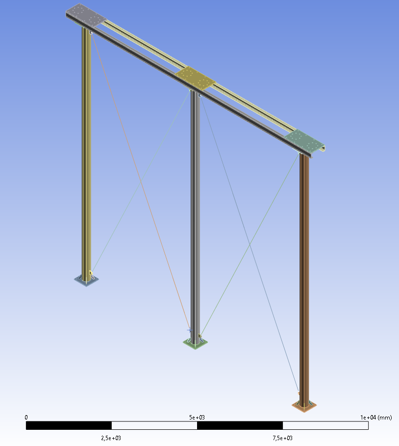
I am running a static structural analysis of a steel frame with two sets of crossing wires:
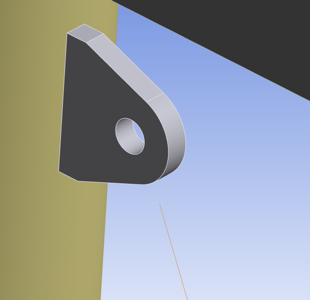
The wires are defined as line bodies where "Model Type" is set to "Cable". Each wire is meshed using only one element. In each corner of the frame, the line body (wire) is to be connected to an ear bracket:
I have tried to manually define a bonded connection between the wire and the bracket using a pinball radius large enough to close the connection. However, this does not seem to be the correct way to do this, considering that wire should be able to move more freely around the axis going through the hole in the bracket. Is using a "Joint" an option here? (I am not familiar with this option).
Later, I also want to run a modal analysis of this frame. Anything special that needs to be taken into consideration when running such an analysis on these wires? (The "Large Deflection" option is not available for modal analysis).
Thank you!
-
April 26, 2024 at 10:19 am
peteroznewman
SubscriberHi,
In this case, using springs is slightly easier. Suppress the four line bodies to try springs.
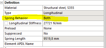
While creating a spring, you simply select the hole surface in each ear. In the spring dialog box, you can type in the pretension value you want the spring to have. You will have to calculate the spring rate of the cable to use in the spring dialog box.
In Workbench, have a Static Structural analysis. Drag a Modal analysis out of the Toolbox and drop it on the Solution cell of the Static Structural. That sets up a Pre-stressed Modal analysis where the pretension in the springs will affect the Modal frequencies.
-
April 26, 2024 at 10:51 am
-
April 26, 2024 at 1:10 pm
ErKo
Ansys EmployeeHi
I would suggest to model it is a cable (springs and cables have very different formulation especially for NL analysis).
Just make the cable longer so they reach the centre of the holes - then use as shown here (slide 16 below) to connect the cable ends to the edge of the hole:
/courses/wp-content/uploads/sites/2/2020/09/Connecting-Bolts-Represented-as-Beam-Elements.pdf
All the best
Erik
-
April 27, 2024 at 11:36 am
peteroznewman
SubscriberFollow Erik’s suggestion for the nonlinear Static Structural part of your analysis to get the behavior of the cables going slack under certain loads.
You observed that Large Deflection is not available in Modal. That is because it is a linear analysis. When Workbench has a nonlinear model, it must linearize it before submitting the model to the solver. Nonlinear contacts that can change from an open state to a closed state during loading of a nonlinear Static Structural model must be converted to be either open or closed during the Modal analysis and Ansys has rules for deciding on how to convert each contact. Similarly, if there is initial tension on the nonlinear cable, I expect they will behave like springs in Modal and any subsequent linear analysis such as Harmonic Response. So even if the deformation in the linear Harmonic Response would have made the cable go slack in the nonlinear Static Structural, I expect that cable will generate compressive forces.
To get a more accurate dynamic response to something like earthquake ground motion where the deformation would cause the cables to go back and forth from tensioned to slack during the simulation, you will need to do that in a full Transient Structural and not use the linearized MSUP methods that use a Modal analysis.
However full Transient Structural analysis takes longer to solve and longer to postprocess. You could start with two linear models, one with cables tensioned and one without any cables to get an upper and lower limit on the linear response of the structure before starting the nonlinear full Transient Structural analysis.
-
- The topic ‘Analysis of steel frame with (tension only) wires?’ is closed to new replies.


-
4678
-
1565
-
1386
-
1242
-
1021

© 2025 Copyright ANSYS, Inc. All rights reserved.


