-
-
March 12, 2024 at 6:24 pm
ROHITH
Subscriberi was trying to do the simulation for Robotic Finger and the results are not generating and im getting error while im trying to solve it i have attached the archived file can anyone look into this and could help me finding the reason for error https://drive.google.com/drive/folders/1SJfYZfe9-9mGwlApHDrDCBod9N8cIPMb?usp=sharing
-
March 12, 2024 at 6:27 pm
-
March 13, 2024 at 7:18 am
ROHITH
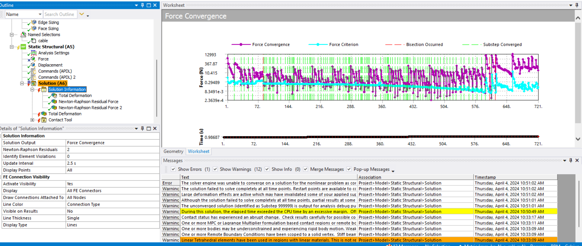
SubscriberTHE SOLUTION IS NOT CONVERGING IN THE INITIAL STAGE ONLY
-
March 13, 2024 at 9:02 am
Ashish Khemka
Forum ModeratorHi,
Can you please share a snapshot of the solver output. Did you try performing a transient analysis?
Regards,
Ashish Khemka
-
March 13, 2024 at 11:38 am
ROHITH
SubscriberNO I TRIED WITH STRUCTURAL
-
March 13, 2024 at 11:43 am
-
March 21, 2024 at 4:03 pm
peteroznewman
SubscriberHere is a discussion on a cable driven joint. It uses rolling contact, but the same techniques apply when you have a revolute joint. This discussion has a link to a model you can download and look at.
-
March 21, 2024 at 4:54 pm
ROHITH
SubscriberI have seen that but in my case the thread is touching the walls it slides over the corner and i need to find friction at that region
-
March 21, 2024 at 6:06 pm
peteroznewman
SubscriberWhat is the purpose of this simulation? What is the output you want the simulation to generate?
Have a closer look at the example cable driven joint I provided. Notice that beam elements were used to mesh line bodies that represent the wire. That is much better than what is in your model which has the wire meshed as solid bodies. This is to be avoided because it creates a model that takes a very long time to solve.
-
March 21, 2024 at 6:26 pm
ROHITH
SubscriberI WANT TO SEE HOW MUCH FORCE IS REQUIRED TO PULL THE THREAD IF I APPLY 1KG LOAD AT FINGER TIP AND WANT TO SEE STRESS IN THE THREAD ALONG WITH FRICTION AT THE CONTACTS AND IN MY CASE THE THREAD IS NOT STRAIGHT IT IS BENT
-
March 21, 2024 at 7:28 pm
peteroznewman
Subscriber1 kg is a mass. You mean supporting a 1 kg mass with the finger horizontal. Where exactly on the fingertip is this 1 kg mass? Nearer to the joint or the tip or in the middle of the fingertip pad?
You want to know the tension in the wire (thread) when this 1 kg mass is being supported.
Please create a cross-section of the links in the YZ plane through the center of the wire in the X direction. Show where the wire touches any part and what locates each end of the wire: the end fastened to the fingertip and the end where the wire is pulled.
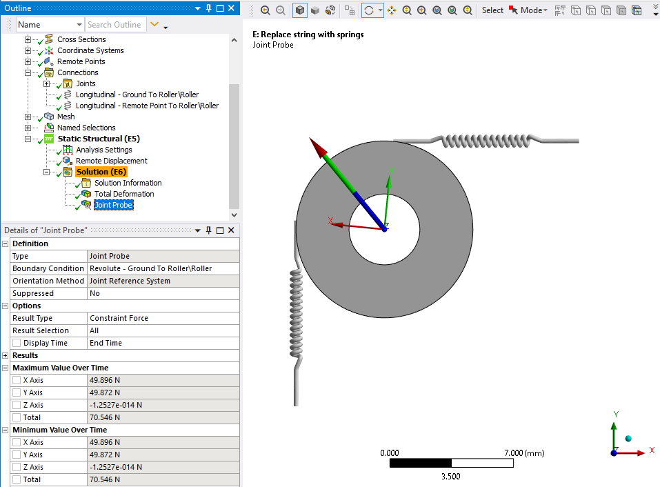
It may be easier to converge if you replace the wire with several spring elements. At the points where the wire bends around a corner, a dummy body will be used to represent that corner. The spring on each side of the corner is attached to the dummy body which will have a revolute joint to the center of the corner radius. The revolute joint can measure the normal force and provide a coefficient of friction at the appropriate radius. This will be much more computationally efficient than trying to get the wire to make frictional contact with the corner.
Instead of using an actual mass and gravity on the fingertip, use a remote displacement instead and just fix Z = 0 leaving all others Free. Then you can pull on the end of the last spring to tension the “wire”. When the reaction force at the fingertip reaches 9.81 N, you will know that the fingertip is supporting a 1 kg mass.
-
March 21, 2024 at 7:47 pm
peteroznewman
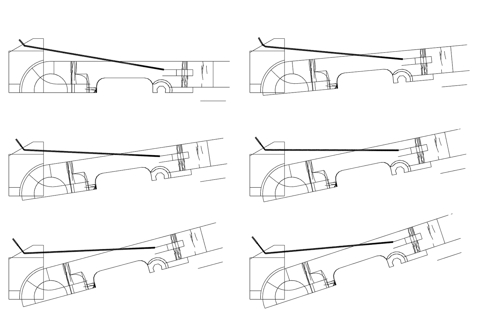
SubscriberHere is a cross-section. The link design has a rotation stop prevent rotating each link back past this extended configuration. The finger can only curl up from this point. In this configuration, a large mass can be supported without any tension in the wire. I assume you want to know the tension needed to curl the fingertip up, is that correct? I don't see a wire to tension to do that. I see a light tan wire that when tensioned could curl the middle segment of the finger up. I also see a wire that could curl the first segment of the finger from the palm. Please clarify which segment of the finger you hope to move to lift the 1 kg mass.
-
March 21, 2024 at 7:54 pm
-
March 21, 2024 at 8:27 pm
ROHITH
Subscriber1st i want to see the stress in wires and contact status without applying any load and i have added spring system to the one end which restricts the finger to curl i have updated the design and added joints and contacts and i have shared the new archive in the same link can you open the file i have replced and check it and the material for the wire is different one and it is not elastic in nature and i even want to see how the wire glides over the edge and bends while the finger is curling and 2 ends which are bent initially makes the lower link to move down and the link under spring system makes the 1st link to curl to make the whole finger move we need to pull all three wires at a time
-
March 22, 2024 at 1:59 pm
peteroznewman
SubscriberYou have drawn a bent wire, and that is the shape that has zero stress before load is applied.
If you were to have a fixed support on the fingertip and simply pull the right end of the green wire in the +Y direction to straighten the wire with no contact with anything else, you would generate bending stress all over the length because you are straightening the wire. The natural shape of the wire is straight. That is the shape that should have zero stress under zero load.
To obtain the correct bending stress in parts that change shape when they are installed in a mechanism, draw the part in the shape that has zero stress, then assemble the part into the mechansim. This is explained fully in this discussion.
For components like wires that have very low bending stiffness but very high axial stiffness, or bicycle chains that have many short links with joints, you can draw the parts in the assembled shape. The problem in your model is your solid wire does not have a very low bending stiffness. It has the same stiffness in every direction. That is why you won't get accurate stress in the wire using a mesh of solid elements with an isotropic linear elastic material model.
-
March 22, 2024 at 5:37 pm
ROHITH
Subscribereven i tried with beam elements and when i m trying to push from one end the beam elements got breaked and came out and i have seen the discussion in that case the belt can we drawn to race track shape due to tension but in my case the wire has to pass through the hole and it wont be possible to draw the wired part whith those bents and i think spring helps in providing the initial tension in the wire
-
March 23, 2024 at 2:33 pm
peteroznewman
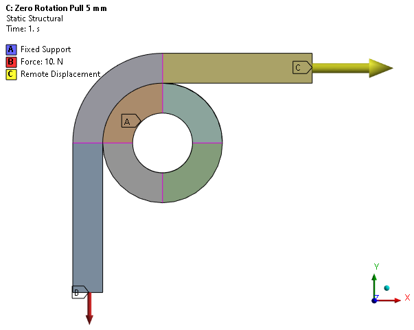
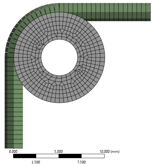
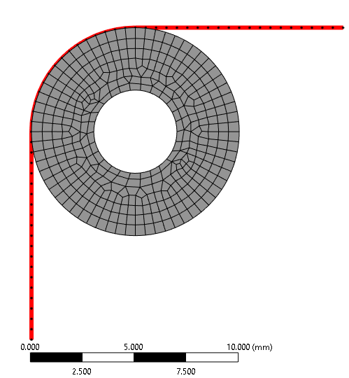
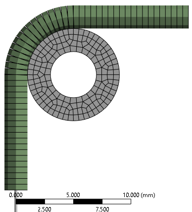
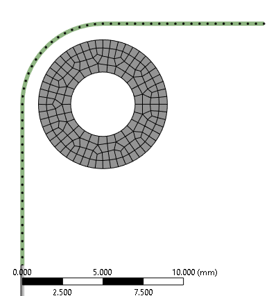
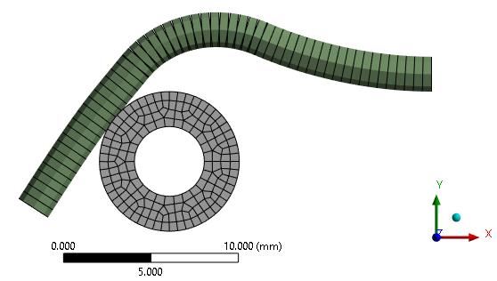
SubscriberRohith, I’m not sure you understood my point about using solid elements, linear elastic materials and drawing wire bent to conform to the path through the mechanism. The bends you draw in the wire remain in the wire as it is pulled around a roller. I created an example to show the behavior of the method you are using. It consists of a wire that has a 10 N downward (-Y) force on the bottom end of the wire that is drawn around a frictionless roller. The other end of the wire is pulled 5 mm along the +X direction. Contact is frictionless between the wire and the roller.
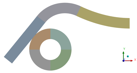
Here is the deformed shape at the end of the simulation.
This model used solid elements, but you would get the same result with beam elements. I hope this makes my point clearly.
You could use the line bodies that allowed you to mesh with beam elements, but mesh with LINK180 elements instead, which have no rotational degrees of freedom and so you can draw them bent and they will straighten just like a bicycle chain straightens when the sprocket turns.
-
March 23, 2024 at 4:02 pm
ROHITH
Subscriberi tried with line bodies as well but it didnt worked as i mentioned when i tried with line bodies the line elements cant be connected each other can you once simulate it and upload the file
-
March 23, 2024 at 5:01 pm
peteroznewman
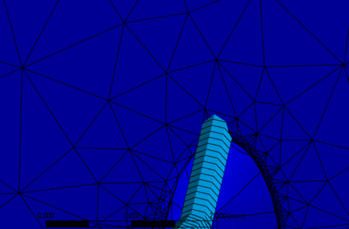
SubscriberHere is the line body meshed with Link180 elements at the start of the simulation:
Here is the simulation after pulling the end 5 mm.
Here is a link to the the ANSYS 2023R1 archive without results.
-
March 23, 2024 at 5:14 pm
ROHITH
Subscriberno i was asking to simulate my finger design by pulling at least 1 thread as in this case the wire has 1 path but in my case i must follow a loop and the thread must glide through the edge of the hole and i find it difficult to do that
-
March 23, 2024 at 6:50 pm
peteroznewman
SubscriberRohith,
I'm willing to advise you on the best path to success for your simulation. Sometimes a few paragraphs may be sufficient to get you turned around and pointed in a better direction than the one you were headed down. Other times, a relevant example is required for you to fully understand the problem with your approach and the benefit of my approach. That is what I did in the example I just provided, which took me a couple of hours to create. Previously, I provided a link to the cable-driven-joint discussion which shows two wires threaded through two holes and the wire bending around the edges of those holes. This model also took a few hours to get working.
I'm not willing to build your model for you, which is very complex and would take me dozens of hours to build. I recommend you study what I provided, apply what you learn and try to move just one link in your finger, suppressing all the other parts. You might need two wires, or at least one wire and an opposing tension or torsion spring on the opposite side of the revolute joint. After you have some success with a single link, you can move on to a second link, however, that can be much more difficult if the design is poorly done such that tension in the wires for the second link creates a moment about the revolute axis of the first link.
Building up the skills to do these simple models is a necessary part of the learning curve and may take weeks to accomplish.
Best of luck!
Peter
-
March 23, 2024 at 7:50 pm
ROHITH
Subscriberok ill try myself and post the doubts in here hope you will be avaliable to help me thanks peter
-
March 25, 2024 at 6:09 pm
ROHITH
Subscriber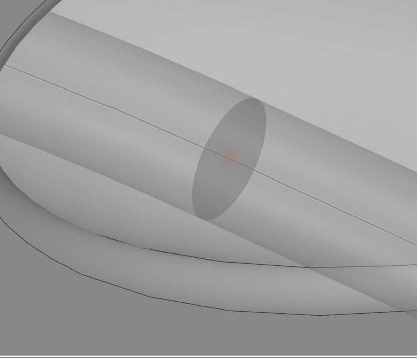
 Hi peter i changed the strings to beam elements and when doing so the beam are not connected properly even though there is no gap and when im trying to connect it the shape of string is disturbing and even trying with share topology feature the other links are getting joined and making a 1 body making difficult to give joint and contacts how to solve this
 -
March 25, 2024 at 6:55 pm
peteroznewman
SubscriberIn SpaceClaim, on the Workbench tab, Unshare All.
Make a Component called Strings and move all the lines representing strings/beams into that component. Do not put any solid bodies in that component. Open that Component in its own window, use the Share button on the Strings.
In this way, only the strings will share topology and should remain connected in Mechanical. They will not be connected to any solid body.
-
March 25, 2024 at 8:47 pm
-
March 25, 2024 at 11:41 pm
peteroznewman
SubscriberThe nodes at the center of the sting do not penetrate the edges of the hole. I suggest you offset the hole surface by the radius of the string then the centerline of the string will be in the correct position when the nodes contact the offset surface. In the first image below, the surface has been offset to reach the nodes at the center of the string. If you turn off the thickness on the beams and shells, you can see that the nodes touch the surface.
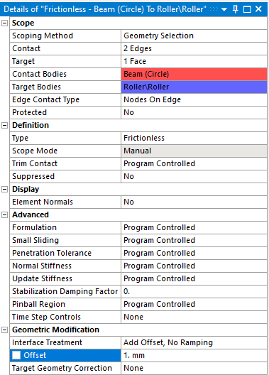
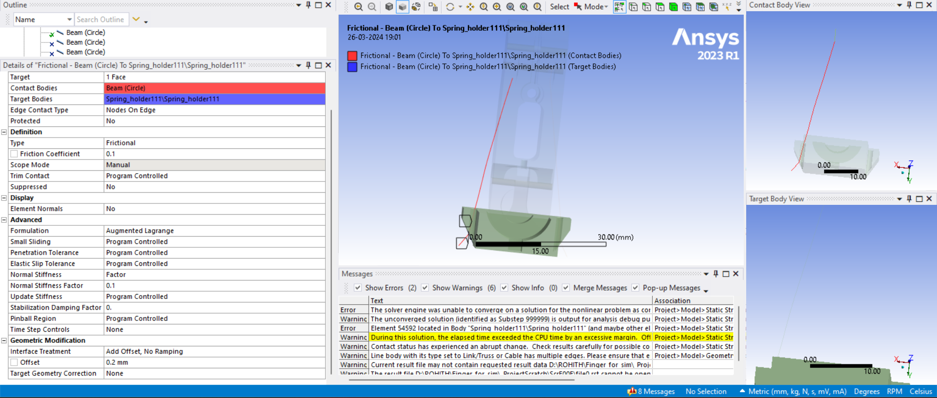
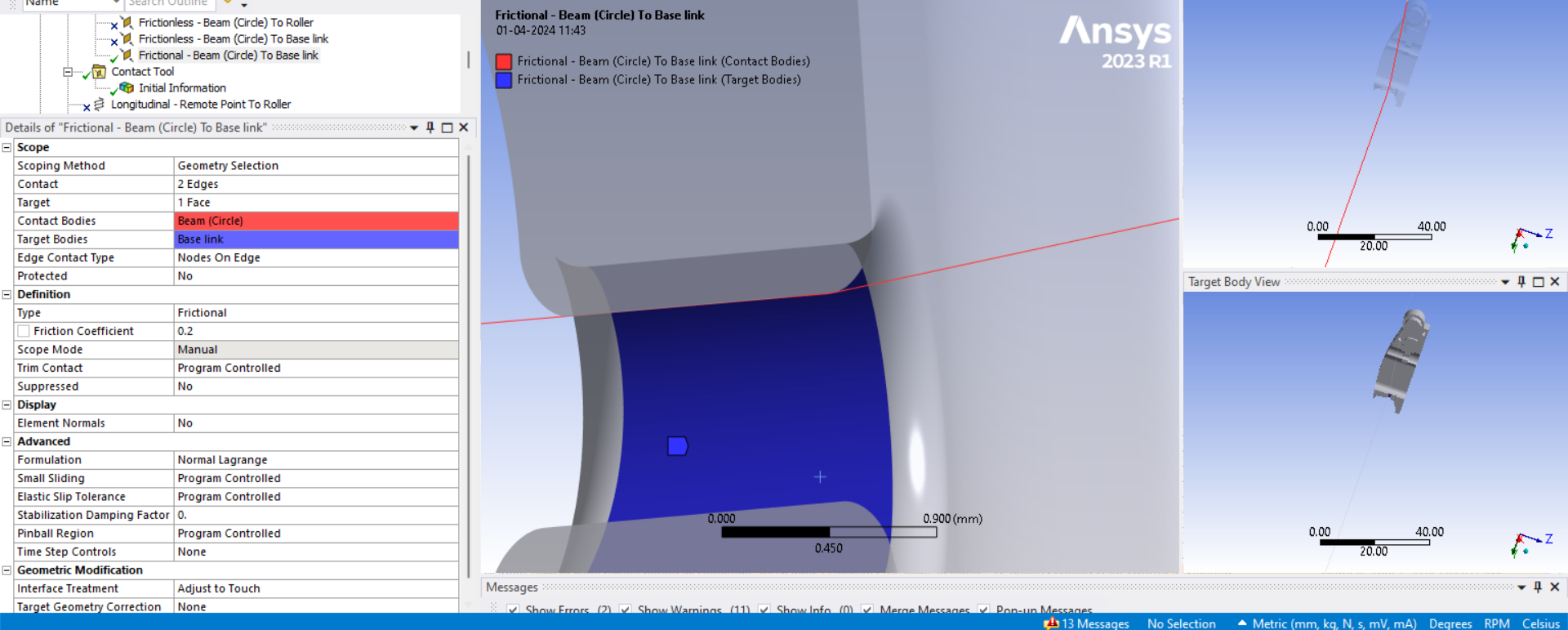
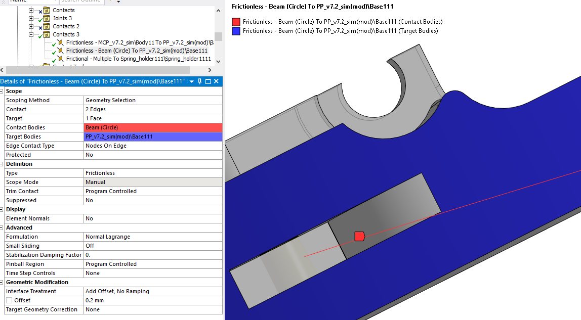
An alternative is to use a setting on the Contact Definition: Add Offset, No Ramping to the Interface Treatement under the Geometric Modification of the Frictionless Contact definition. In the image below, with the thickness turned on, it seems like the string sits on the roller. But in the next image, you can see that the nodes are offset from the surface.
-
March 26, 2024 at 5:05 am
-
March 26, 2024 at 12:33 pm
peteroznewman
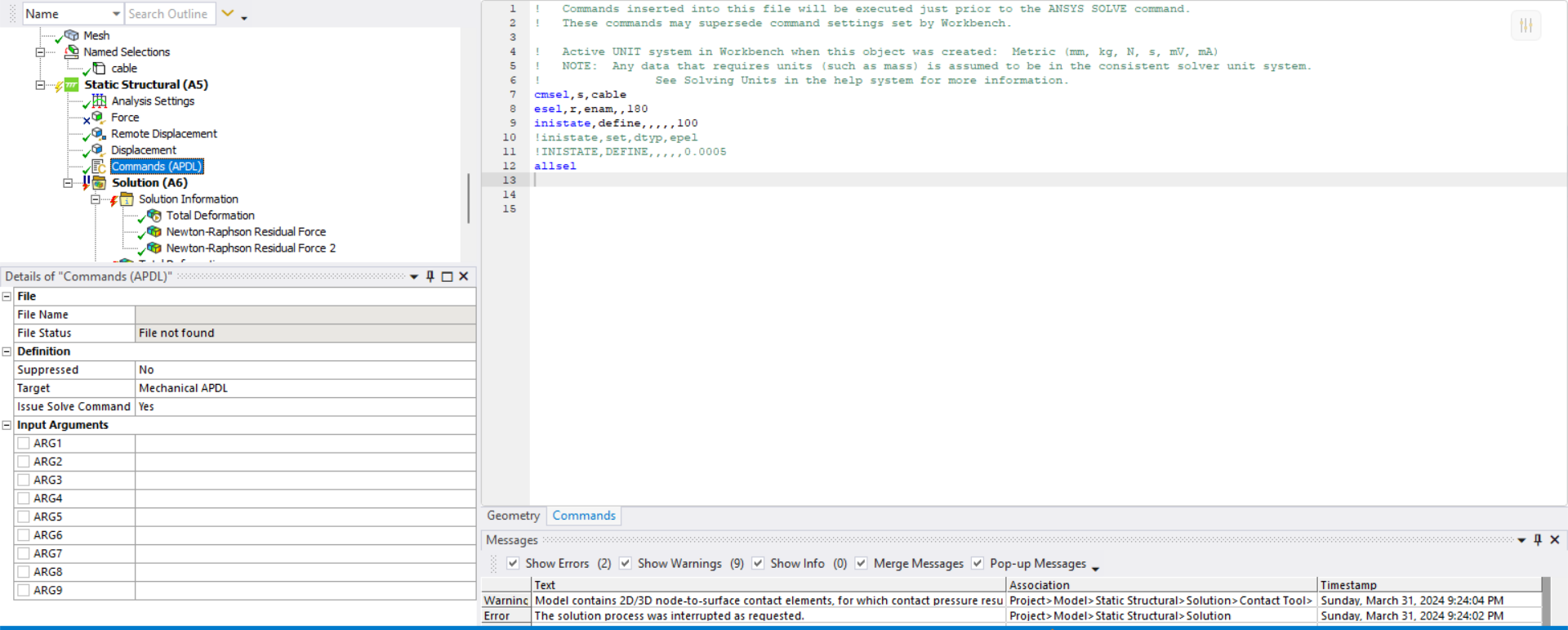
SubscriberIf you study my model, you will notice a Command object under the Static Structural branch with the command
neqit,100
which causes the solution to keep trying for 100 iterations instead of stopping after 26 iterations. This may help in your model.
Does your model use Link180 elements or Beam elements on the line bodies of the string?
-
March 26, 2024 at 12:39 pm
ROHITH
Subscriberi used beam elements i didnt get to know how to create link 180 element and the iterations are getting stopped when the wire is getting in contact with the edge and i even tried by giving the command of 100 iterations same result and can you once check the archive file that i re uploaded with all changes in the same link
-
March 26, 2024 at 12:58 pm
peteroznewman
SubscriberReread my reply earlier in this discussion when I said a Beam model will give the same result as a Solid model of the string when pulled over a roller.
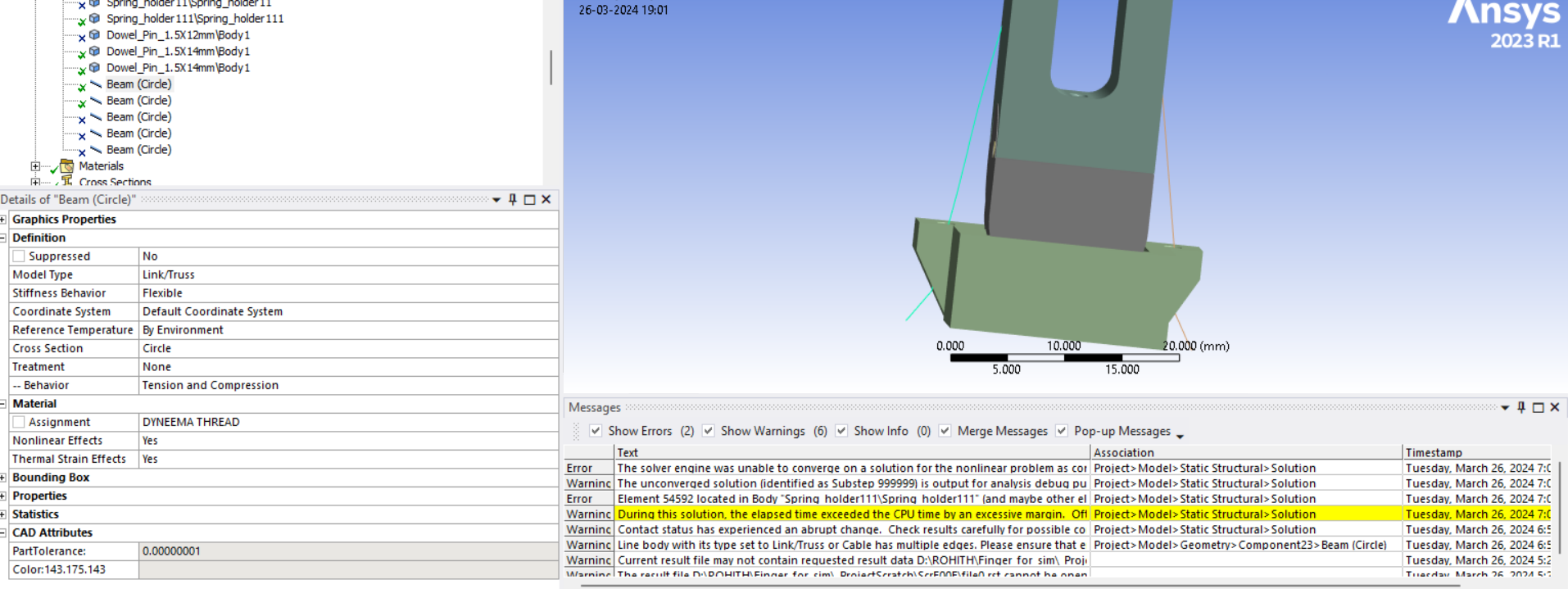
If you study my model, under the Geometry branch, click on the Beam (Circle) object and in the Details window, you will see Model Type where you can change a Beam to a Link/Truss element.
I shall warn you that since you found it difficult to obtain convergence with Beam elements, you will find it 10 times more difficult to obtain convergence with Link elements. The reason is the shape of a chain is unstable unless it is under tension. Extra effort is required to put the Links under tension before any movement can occur. A string of beam elements is stable on its own if you hold one end fixed.
Reread the paragraph above beginning with "It may be easier to converge if..." that I wrote in the March 21, 7:28 am reply.
-
March 26, 2024 at 1:32 pm
-
March 26, 2024 at 3:41 pm
peteroznewman
SubscriberI don't recommend you use Link/Truss elements because they are much more difficult to achieve convergence, but if you want to try, you should start with the simplest model possible, one link, one revolute, one string, and one spring. You will need to take special care to create tension in the string as I did in the example I provided.
I recommend you replace the string with several spring elements. At the points where the string wraps around a corner, a dummy body will be used to represent that corner. The spring on each side of the corner is attached to the dummy body which will have a revolute joint to the center of the corner radius. The revolute joint can measure the normal force and provide a coefficient of friction at the appropriate radius. This will converge much more easily than the string modelled as Link elements making frictional contact with the corner.
-
March 26, 2024 at 3:58 pm
ROHITH
SubscriberYOU MEAN SPRING ELEMENTS MEANS LINK/TRUSS ELEMENTS AND HOW TO CREATE DUMMY BODY AND HOW TO ASSAIGN REVOLUTE JOINT THERE
-
March 26, 2024 at 9:17 pm
peteroznewman
SubscriberHere is an example where the many Link elements have been replaced by 2 spring elements. The roller has become a rigid body with a revolute joint at the center. The ends of the spring are scoped to the rigid body. This kind of model is useful to evaluate the forces in the mechanism at a particular configuration. It is not as versatile to operate the mechanism through large angles of rotation of the joint, but it is easy to build and easily converges.
-
March 27, 2024 at 4:59 am
ROHITH
Subscriberbut the model im trying to simulate includes threads which have high stiffness and wont stretch easily but you are telling me to do it with springs how can this be useful in my case
-
March 27, 2024 at 11:29 am
peteroznewman
SubscriberYou can type in a high stiffness value for the springs. Spings are useful because they converge very easily.
You could instead draw a line body where each spring goes. Make sure to mesh with exactly 1 Link element on each line. Connect the end of the line to the diameter of the rigid roller. The effect will be the same as the spring but will be a lot more work.
-
March 27, 2024 at 5:35 pm
ROHITH
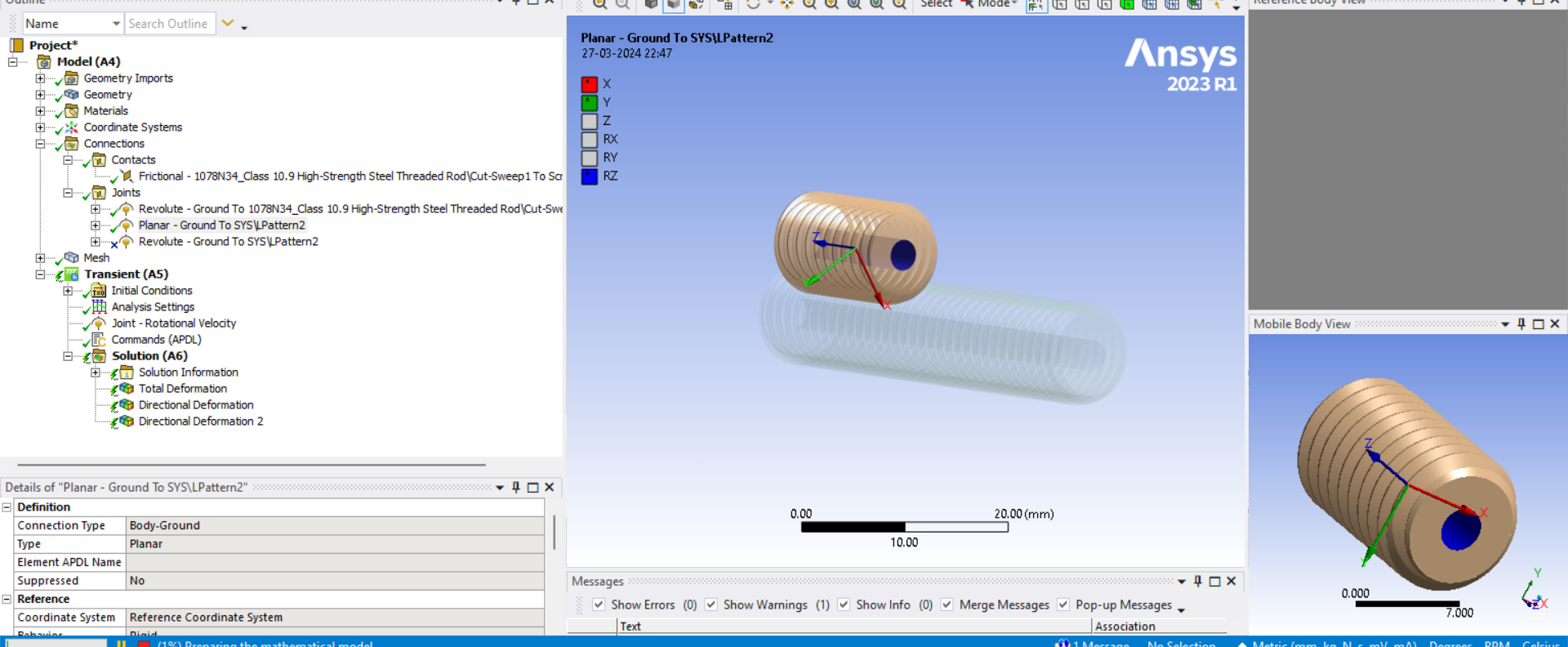
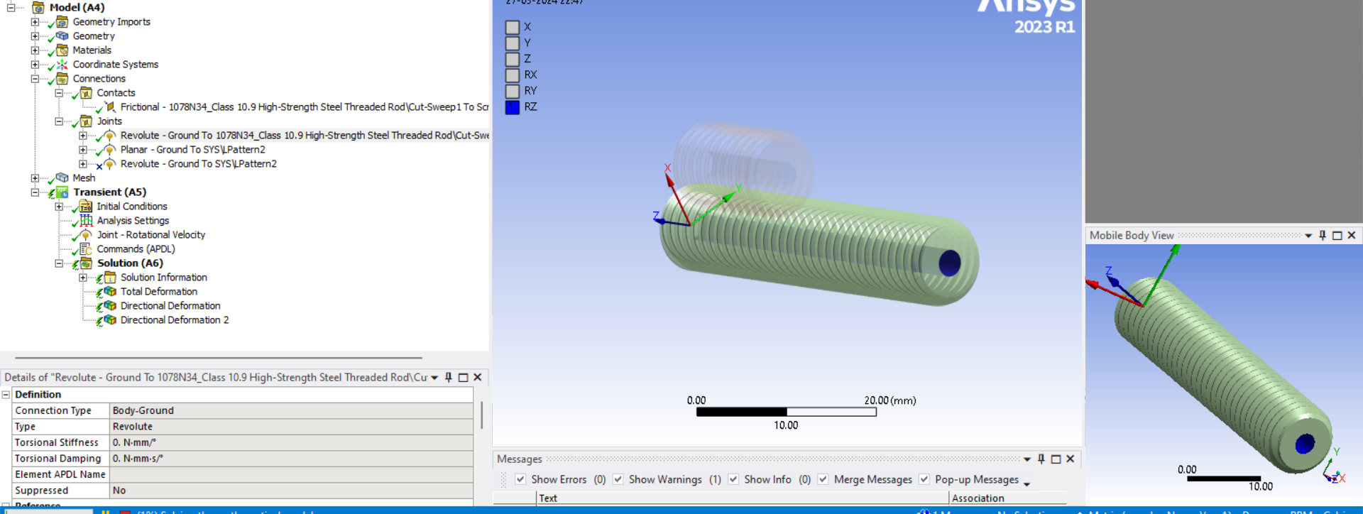
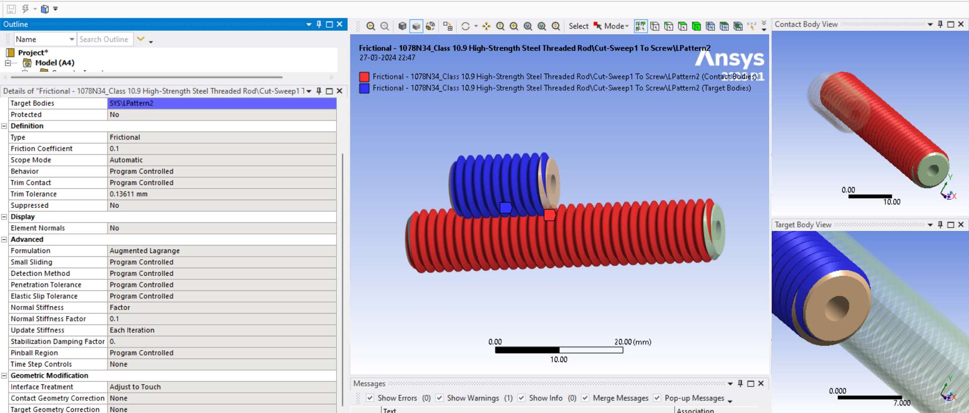
SubscriberHey peter just a small doubt i need to simulate small screw to rotate about its own axis and revolve around the central screw i tried by changing the positions of the joint but it didnt worked could you juat check my archive file once and suggest me changes required SCREW
-
March 27, 2024 at 10:09 pm
peteroznewman
SubscriberThe small scew orbiting a central screw is similar to a nut on a central screw. As the nut rotates, it travels along the axis of the central screw.
Link to a discussion that shows how to convert a Cylindrical Joint to a screw joint using some APDL code to represent a nut on a screw.
A joint is much preferred over using Contact to achive the desired motion.
-
March 30, 2024 at 12:37 pm
ROHITH
SubscriberHI PETER I CHANGED THE WIRES TO CABLE ELEMENT AND ATTACHED SPRINGS AT THE END TO MAKE IT LOADED WITH STIFFNESS VALUE OF 1 EVEN THOUGH IT IS NOT SOLVING WHEN THE INTERFERENCE TREATMENT WAS GIVEN WITH ADJUST TO TOUCH IT IS BEHAVING LIKE THIS AND WHEN I GAVE ADD OFFSECT NO RAMPING THE STRINGS ARE PENETRATING INSIDE THE BODY IM NOT GETTING ANY IDEA LIKE HOW TO SOLVE THIS COULD YOU JUST HELP ME IN THIS
-
March 30, 2024 at 5:37 pm
peteroznewman
SubscriberStart with just one moving link with a revolute joint to a fixed link. Choose a link that has the fewest bends in the wires. There should be two wires, one to move the link up and the other wire to move the link down. Suppress all other links and all other wires.
The idea of using springs is that they replace a wire, they are not added to the end of the wire. Springs do not wrap around corners, two springs are used to go around a corner, one spring attaches at the tangent to the input side of the corner and the other spring attaches at the tangent to the output side of the corner. A roller body with a revolute joint is used to model the corner and transfers the tension in one spring to the other spring that exits at a different angle. If you have one corner the up wire wraps around and another corner the down wire wraps around, then you will have four springs and two rollers to represent the two wires wrapping around two corners.
In my example model, I demonstated one “wire” wrapped around one “corner” by using two springs attached to a roller on a revolute joint. This is a revolute joint at the corner and is different from the revolute joint the link is rotating around.
-
March 30, 2024 at 5:50 pm
ROHITH
SubscriberI DIDNT GET LIKE WHAT YOU ARE TELLING ME TO DO WITH THE SPRINGS AND I SUPPRESSED AL OTHER COMPONENTS EXCEPT 1 WERE AND 1 REVOLTE JOINT BETWEEN THE LINK COULD YOU JUST MODEL THE THING YOU ARE SAYING WITH THE SPRINGS IN MY PROBLEM I HAVE ATTACHED THE LINK FOR THE FILE HERE FINGER
-
March 30, 2024 at 6:30 pm
peteroznewman
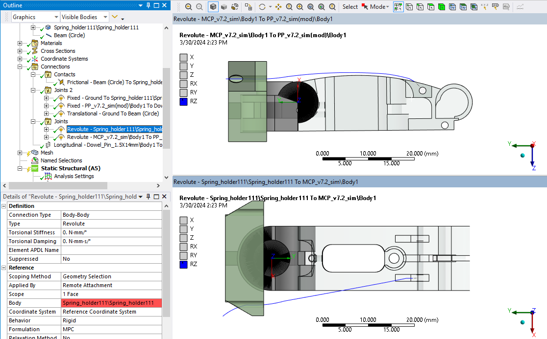
SubscriberIn the archive, there is one wire, but two revolute joints. Tension on that one wire is going to affect both joints. This is unsuitable for the simplest example.
Keep the revolute in the top viewport and change the revolute in the bottom vewport to Fixed. One wire can only move the link up. There should be another wire that will move the link down. For now, we will just work with one wire.
-
March 30, 2024 at 6:54 pm
ROHITH
SubscriberTHE WIRE THAT IS THERE WILL MOVE THE LINK SIDE WAYS EACH WIRE EACH SIDE AND IF WE PULL BOTH AT AT TIME IT MOVES THE LINK DOWN AND RTO MAKE IT MOVE UP THE SPRING TAKES CARE OF IT SO IF TO WORK WITH ONLY ONE WE CAN SUPPRESS THE REVOLUTE JOINT THE ONE YOU SHOWN IN 1ST PICTURE
-
March 30, 2024 at 7:22 pm
peteroznewman
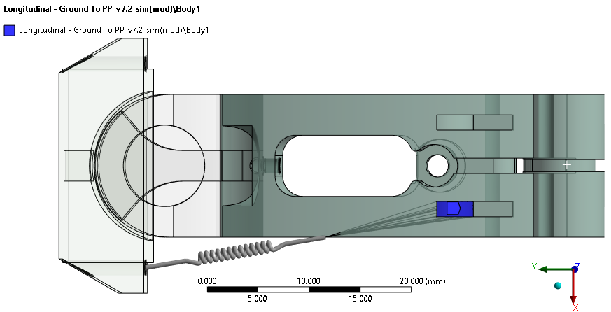
SubscriberHere are the results of a simple model using a spring to determine the tension in the wire when there is a 9.8 N (1 kg mass) on the next joint in the finger. You can see the wire has been replaced with a spring. The spring has a line of action that makes it tangent to the surface of the finger the wire would be tangent to if it were wrapped around that surface and anchored further to the right. The other end of the spring is tangent to the hole in the fixed part.
The unknown is the tension in the spring under this load. This simple model quickly calculates this value to be 64.7 N
The spring rate is a large number to prevent large movement of the link so the tip of the link only moves 0.12 mm.
-
March 30, 2024 at 7:45 pm
ROHITH
SubscriberBUT IN THIS CASE YOU ARE NOT PULLING ANY THING AND I WANT TO SEE THE BEHAVIOUR OF THE STRING AROUND THE EDGE AND THE FRICTION THAT IS GETTING GREATED THERE BUT WITH THIS MODEL I CANT GET ANY OF THIS AND THE LINKS ARE NOT EVEN MOVING I WOULD LIKE TO SEE THE BEHAVIOUR OF STRING WHEN IT IS PULLED OVER THE EDGE EVEN THOUGH IT HELPS ME TO GET THE TENSION BUT I NEED TO SEE WITH STRINGS WHICH IS EXACTLY MY PURPOSE OF THE PROBLEM
-
March 30, 2024 at 9:12 pm
peteroznewman
SubscriberComplex models are often assembled using a large number of simple components. I demonstrated how several simple components work.
The component using Link/Truss elements has the benefit of being able to wrap around surfaces and slide on corners but the drawback is they are very difficult to achieve convergence, which can become exponentially more difficult as you add a large number of them into a complex model.
The component using Spring elements has the benefit of very easy convergence and provides the most important information but has the drawback of missing some information which would have to be obtained by other means. However a model with lots of springs is not likely to have convergence problems.
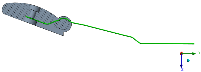
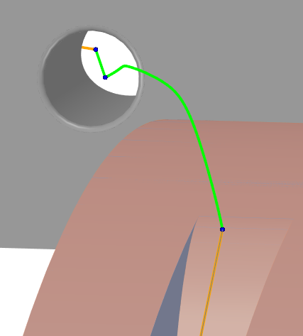
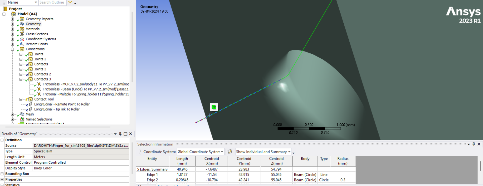
If you really want to use a wire, you must be precise in constructing the wire so that it is drawn tangent to the surfaces it must slide on. Below is the cross-section of the wire. Note that it is not tanget to the surface of the finger and is not tangent to the hole in the fixed part.
The wire must be perfectly straight from one tangency point to the next. You can’t draw any curves unless the wire is in contact with a curved surface, and in that case, the curvature must match exactly. You can’t draw wiggly wire as shown below. The consequence of doing so is that convergence becomes impossible.
Below is an example of a straight wire that wraps on the surface of the link.
To construct the line on the surface of the link required a lot of geometry construction. First a 3D line from one point to another, then a plane on that 3D line, then split the surface on the top of the link with the plane then extract that curve which is an ellipse, then draw a line from the edge of the hole to the tangent point on the ellipse. That is a lot of work for just one section of one wire.
The nice thing about springs is they are straight lines between two points and even if the end points are not exactly at the tangency point, the solution will easily converge and you will get some useful information.
-
March 30, 2024 at 9:38 pm
ROHITH
SubscriberOK THEN MODELLING THE STRING IS THE PROBLEM IN THIS CASE. IF I COULD DRAW THE STRING WITH ALL THE CONSIDERATIONS YOU MENTIONED THEN IT WOULD SOMEHOW BRINGOUT THE RESULT, RIGHT. BY ANY MEANS COULD YOU JUST MODEL ONE STRING AND SOLVE THE PROBLEM IN WHICH THE STRING SLIDE AROUD THE OUTER CORNER WHERE IT BENDS IT COULD HELP ME A LOT IN MY TASK AND HELPS ME FURTHER MOVING FORWARD WITH OTHER STRINGS
-
March 30, 2024 at 10:24 pm
peteroznewman
SubscriberReread my previous reply because I added some information after you wrote the reply above.
You need to develop your geometry construction skills. This one wire you chose has many complicated planes and lines of action. It would be easier for you to construct a correct wire if you choose a simpler wire segment that is limited to one plane and bends around simple blends. Just draw the wire on the surfaces or as straight lines in the air between contacts.
-
March 30, 2024 at 10:41 pm
ROHITH
SubscriberITS NOT ABOUT THE GEOMETRY BUT THE SEETINGS AND APPROACH YOU FOLLOW TO SOLVE THE PROBLEM I THINK IT WOULD BE A BREAT HELP IF YOU SOLVE ONE OR JUST SHARE THE ARCHIVE FILE WITH ALL SETTINGS SO THAT I CAN REFER AND APPLY IT TO ALL OTHER STRINGS
-
March 31, 2024 at 1:04 am
peteroznewman
Subscriber -
March 31, 2024 at 9:07 am
ROHITH
Subscriberill try to modify the geometry but i need to know how solve the problem with the modified geometry because i didnt understand what you meant of using revolute joint at the corners, virtual body and all if you could make one ill try to understand it and apply to all other
-
March 31, 2024 at 11:21 am
peteroznewman
SubscriberFor the method of using springs instead of wires, I sliced off a piece of the body and colored it purple to act as a "roller". I will put a revolute joint between that cylinder and the adjacent part of the link. The springs will model the straight part of the wire. This allows the springs on each side of the roller to have the same tension. For the method of using wires, slicing off a piece is not necessary as the wire would slide on the surface of the boss in the link.
-
March 31, 2024 at 11:22 am
peteroznewman
SubscriberFor the method of using springs instead of wires, I sliced off a piece of the body and colored it purple to act as a "roller". I will put a revolute joint between that cylinder and the adjacent part of the link. The springs will model the straight part of the wire. This allows the springs on each side of the roller to have the same tension. For the method of using wires, slicing off a piece is not necessary as the wire would slide on the surface of the boss in the link.
-
March 31, 2024 at 11:51 am
ROHITH
Subscriberpeter could you just share me the archive file link i want to understand contact settings, joints and other parameters in solving the problem using wire for any of the string like the one you have modeled to pull side ways -
March 31, 2024 at 12:51 pm
peteroznewman
SubscriberBelow is the method of using springs. This is the one that easily converges and provides the tension in the wire for an applied load. The springs attach at the tangent points.
There is a tip load of 9.8 N. The Displacement is X=0 to support the tip because I cut the model in half. The Remote Displacement pulls on the spring to lift the finger tip.
Frictionless contact prevents middle link from back bending.
The spring probe shows the springs need 54.77 N of tension to lift the 9.8 N on the finger tip.
Here is the ANSYS 2023 R1 archive of the spring method. I understand you want to see the method of using wires, but that is much more difficult to converge. The wires needed to attempt the wire method are in the archive as suppressed bodies. You are welcome to try it. I don't recommend it for this model.
-
March 31, 2024 at 12:58 pm
ROHITH
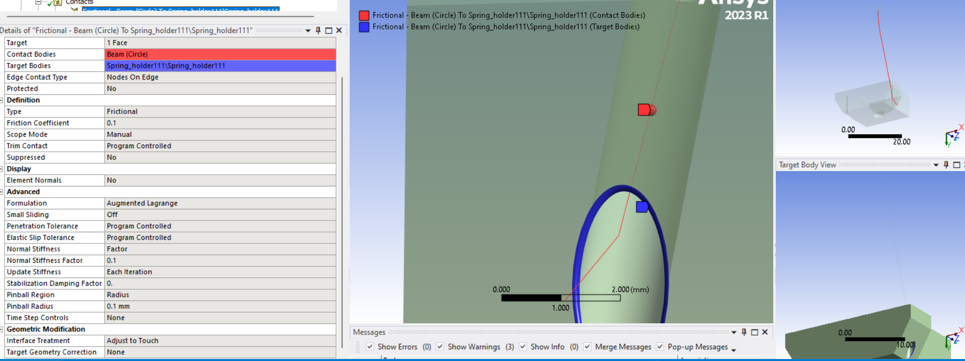
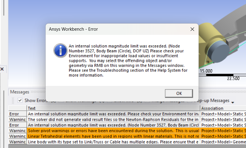
Subscriberthanks peter but i want to solve with wires and want to know the contact stress and behaviour of wire at edges i the file the wires are suppressed but they are not assaigned with any contacts or loading conditions i cant understand how to give pre tensions and contact settings for those could you just solve with the wire which is passing through the edge which i find it more difficult even to assign the settings. i just want to understand the conditions you apply for link elements
-
March 31, 2024 at 2:36 pm
peteroznewman
SubscriberDid you use the INISTATE command?
-
March 31, 2024 at 4:05 pm
-
March 31, 2024 at 6:22 pm
ROHITH
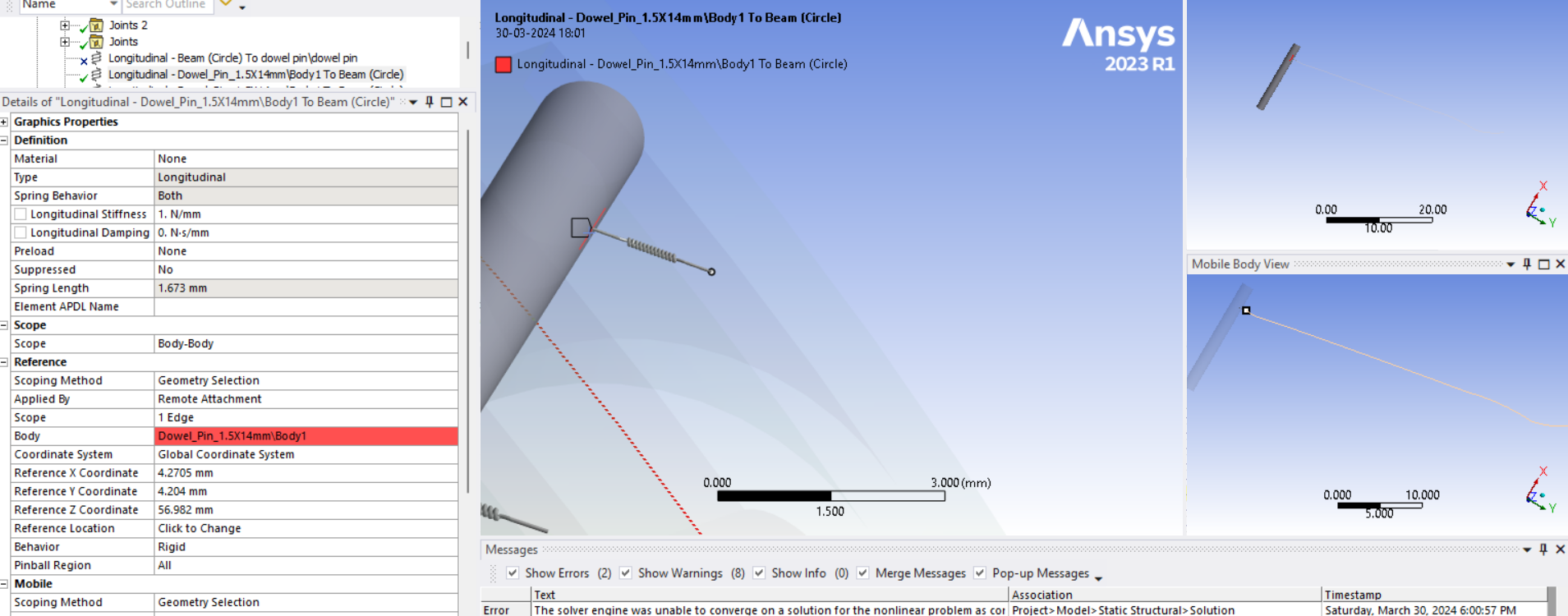
Subscriberwhen i was trying to pull the end of the wire that i have model mostly straignt and tangent to surface it is penetarting into the link and the contact status is closed in initial condiction what could be the reason for this kind of behaviour could you just check this once wire model
-
March 31, 2024 at 7:04 pm
-
April 1, 2024 at 6:17 am
-
April 1, 2024 at 10:51 am
peteroznewman
SubscriberConvergence with Link/Truss or Cable elements is very difficult if you have perfect geometry and impossible with imperfect geometry.
With perfect geometry, it is often required to have several steps, where step 1 does not apply any loads such as displacements, but holds the value at 0. Step 1 has Initial substeps set to 100 to allow the contact to be established while the INISTATE command adds a small amount of strain to the perfect geometry.
One way to help stabilize the model is to hold the fingertip from moving in the Z direction by using a Remote Displacement. Promote it to a Remote Point for later use. Solve the model and obtain the Reaction Force of that Remote Displacement. If it is large, then the tension in the wires is unbalanced. You can set a Remote Force on that Remote Point to be equal to the reaction force found earlier and have that on in step 1 and 2. You can Deactivate the Remote Displacement in Step 2 and the forces in the mechanism will be balanced after the constraint is removed.
Do you see how much work is required to use wires? None of that is required if you use the Spring method.
-
April 1, 2024 at 1:53 pm
ROHITH
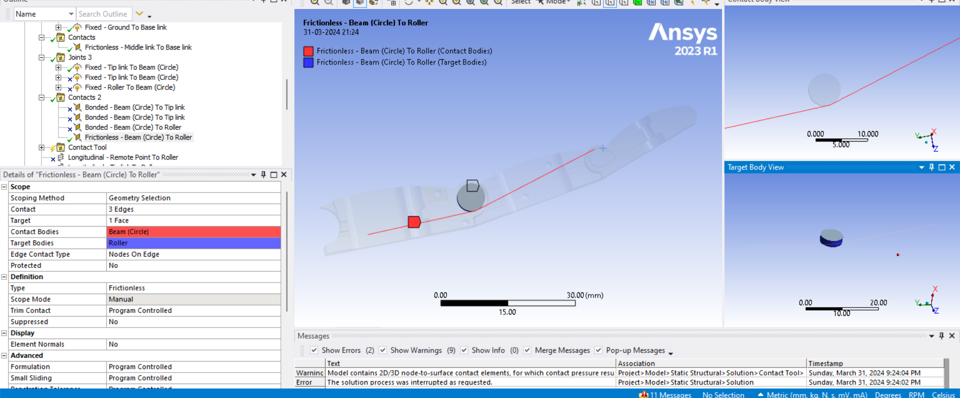
Subscriberyes peter but my project includes the behaviour of the wire i need the contatct stress, tension which are from the wire model only and the one which i have mentioned above worked when i moved the center wire little down but as mentioned i not getting solution for wire which is passing through edge of the link when pulling from one end i have modeled the wire with mostly straight elements and it is tangent to the top link surface but i cant to able to obtain the solution i have attached the pictures of my contact settings and boundry conditions with the lin to archive file edge sliding
-
April 1, 2024 at 10:03 pm
peteroznewman
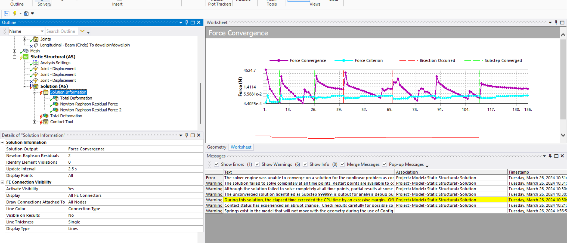
SubscriberIf you extrapolate the trend, you would predict that the lines will cross and the solution will converge, if only the solver would have kept iterating! Can you think of the place where you told it not to give up until 50 iterations? Why don't you change the number from 50 to 100 and see what happens?
I initially did some work on the wire that goes off at an angle to the side while wrapping around the arc of that link. It seemed to me that the wire is on the verge of sliding off the arc and ending up at the side of the link instead of on top. That kind of sudden change in contact status is toxic to convergence. This is not a good design. The link should be wider at the base so there is no chance that the wire will slide off the edge. Bad designs are harder to simulate than good designs.
To address the need to know the contact stress of the part the wire slides on, I would build a dedicated model just for that. It would be a very simple model like the ones I provided above. I would make it a parametric model that will create any of the wire contacts in the assembly. The parametric inputs are the bend radius, the wrap angle and the tension. Using the Parameter set capabilities of Ansys Workbench, you can copy/paste a spreadsheet with as many rows of inputs as you like, then click the Update All Design Points and Ansys will automatically build each of those models and solve them to report the contact stress. The system model of the entire finger (using springs) computes the wire tension values for any load in any configuration. The system model can also be a parametric model to assemble the links in all configurations of interest. By separating the analysis into two models, each one converges easily. This is a great approach that is a widely used by analysts in many fields.
-
April 2, 2024 at 1:40 pm
ROHITH
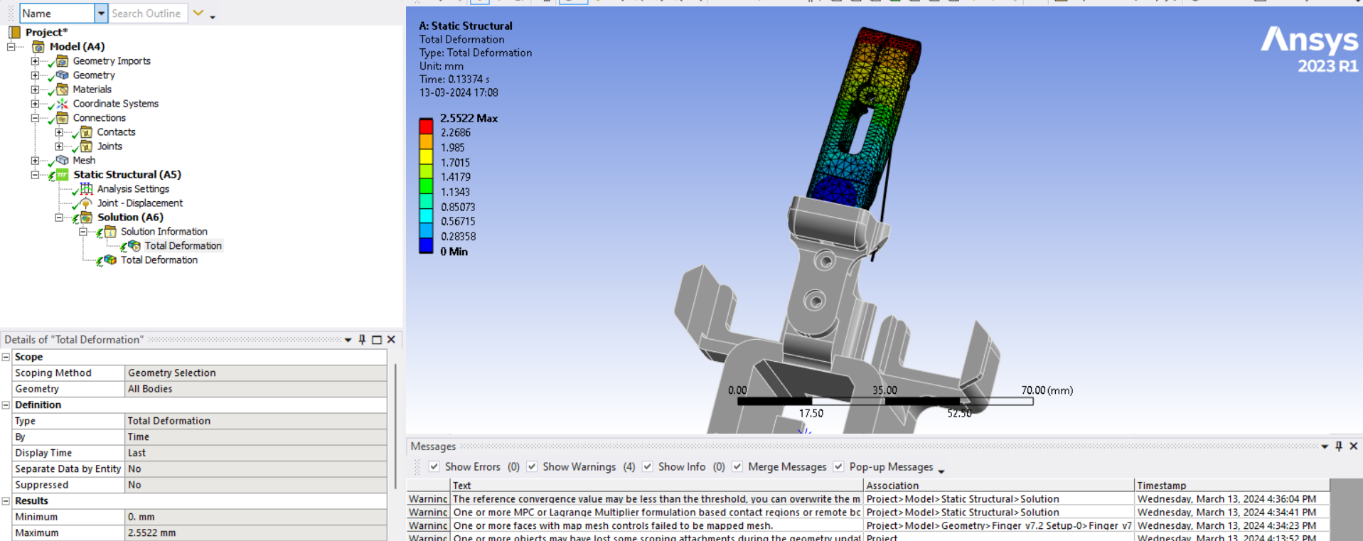
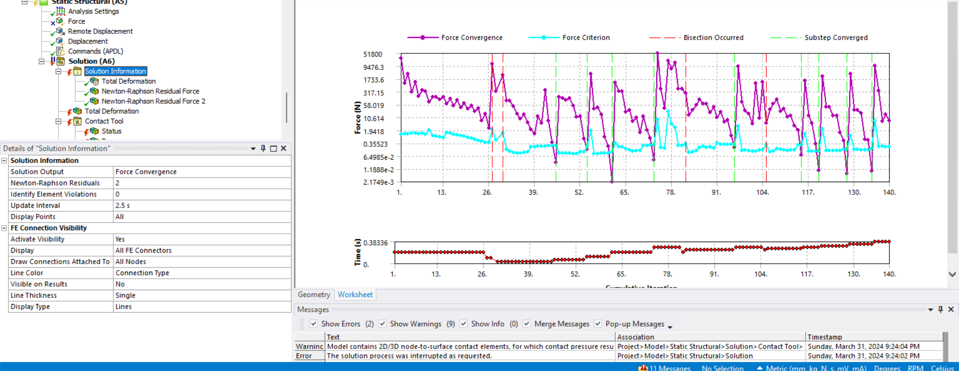
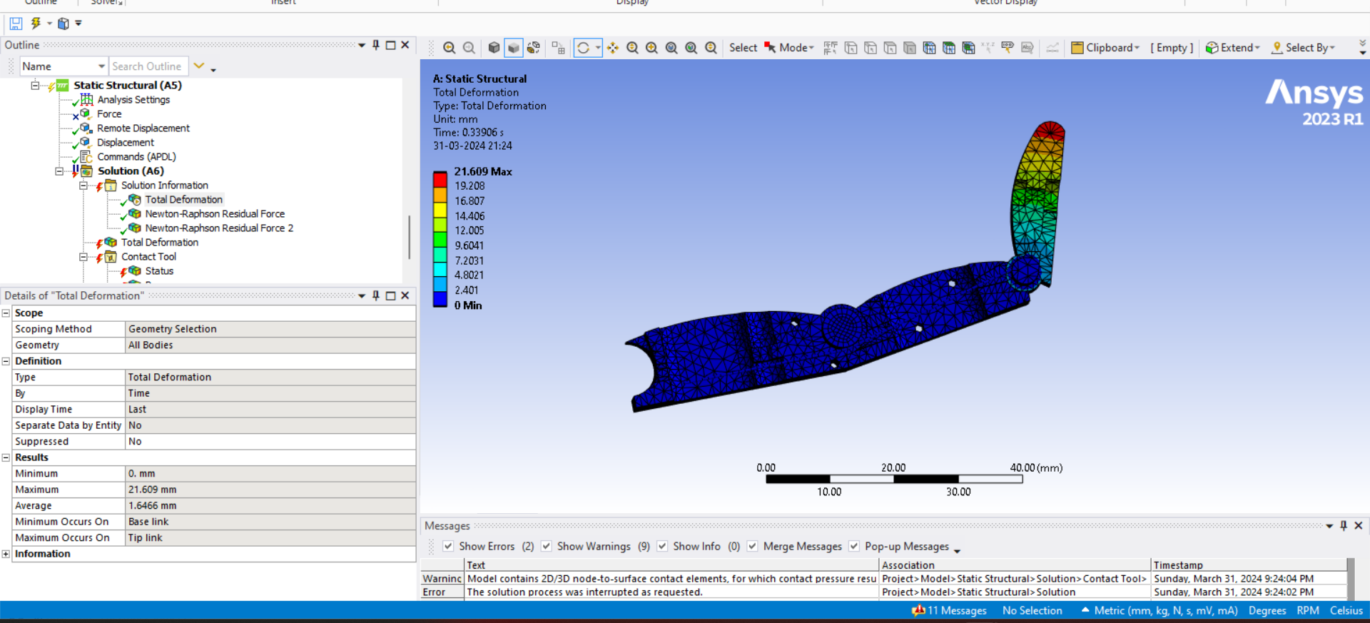
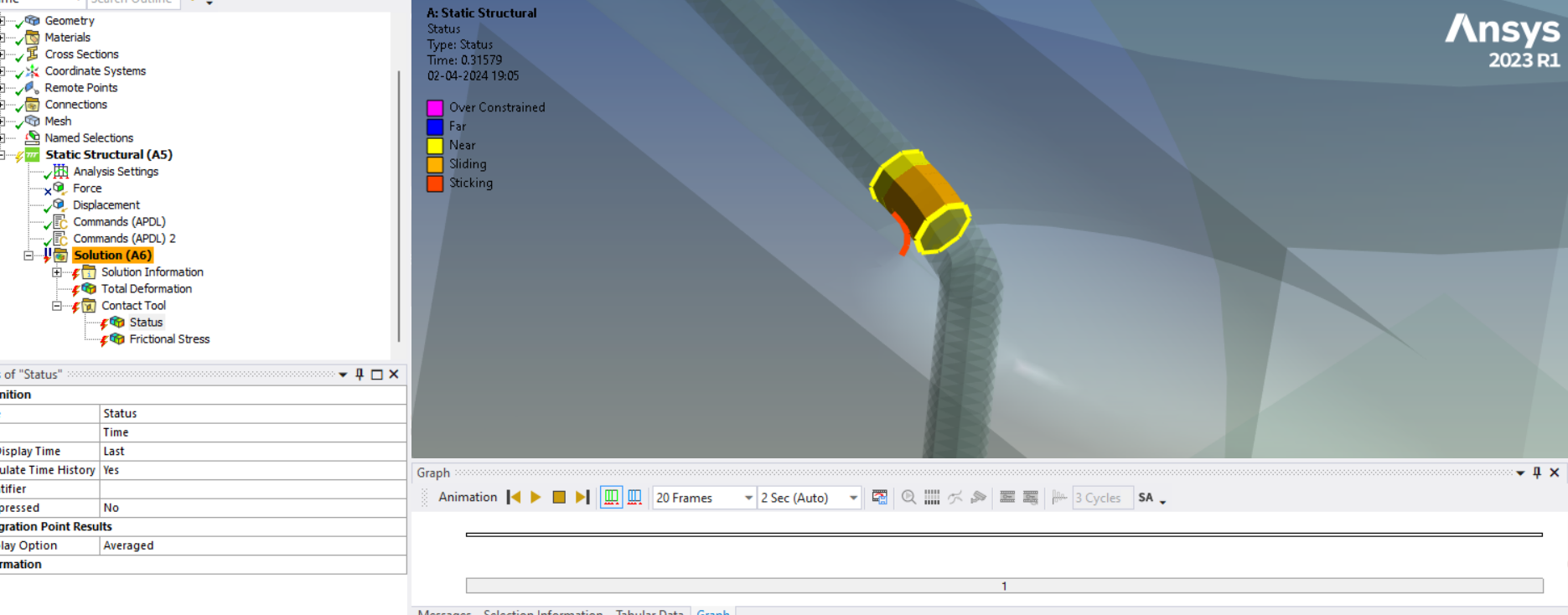
SubscriberHey Peter, I tried to make the wire model as tangent as possible to the edge where it gets wrapped. The solution converged until 1 sec, in which the wire glided along the edge with wrapping but after that, the solution is not converging and terminated could you find the reason for it edge
-
April 2, 2024 at 11:52 pm
peteroznewman
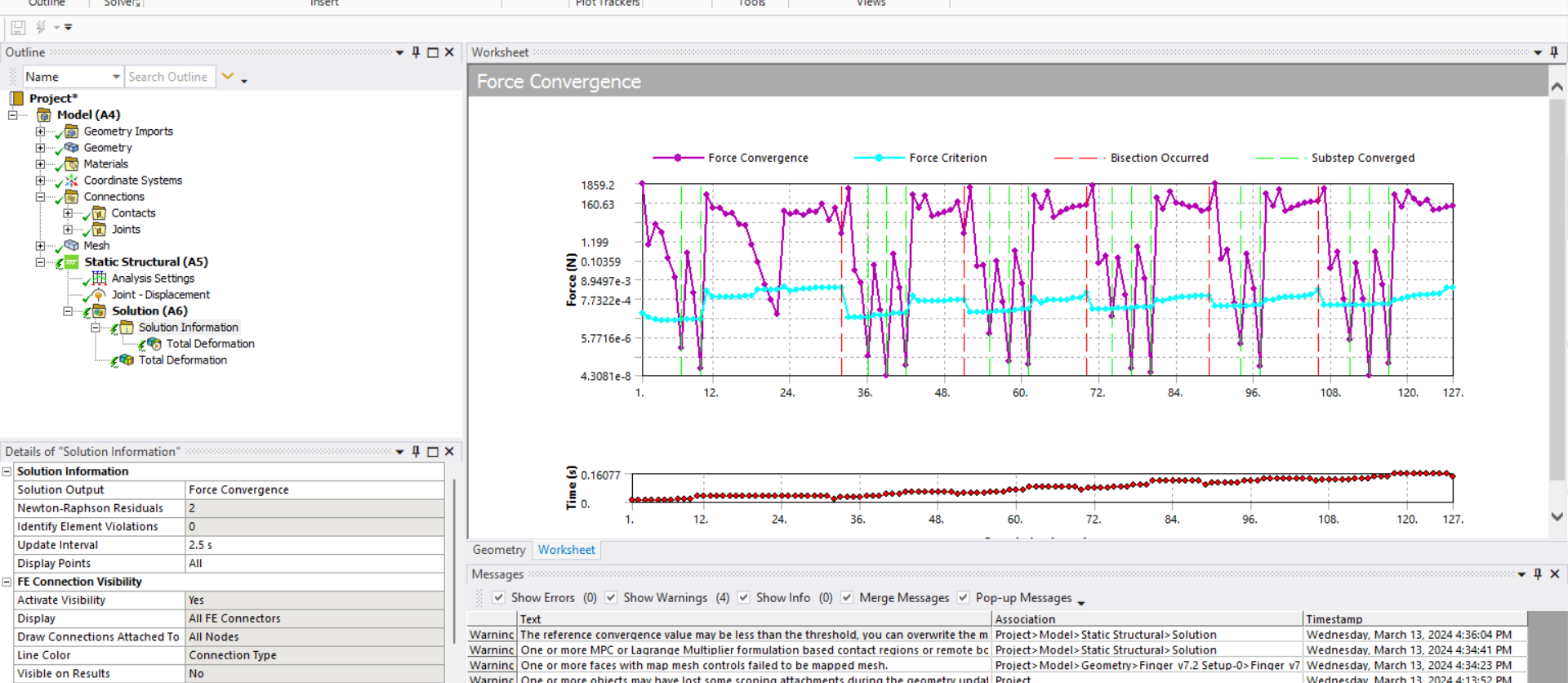
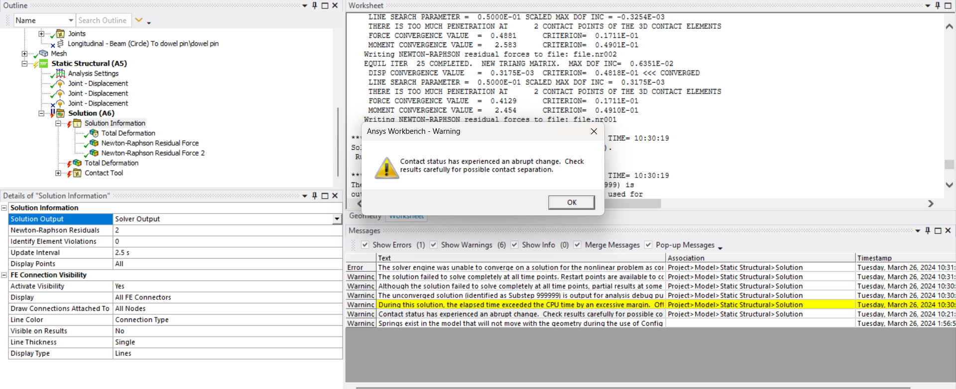
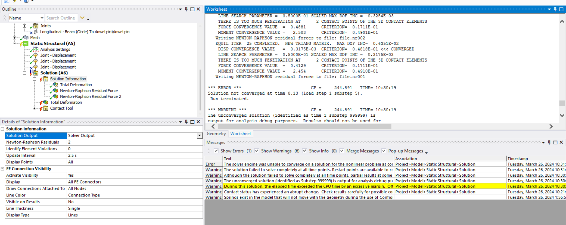
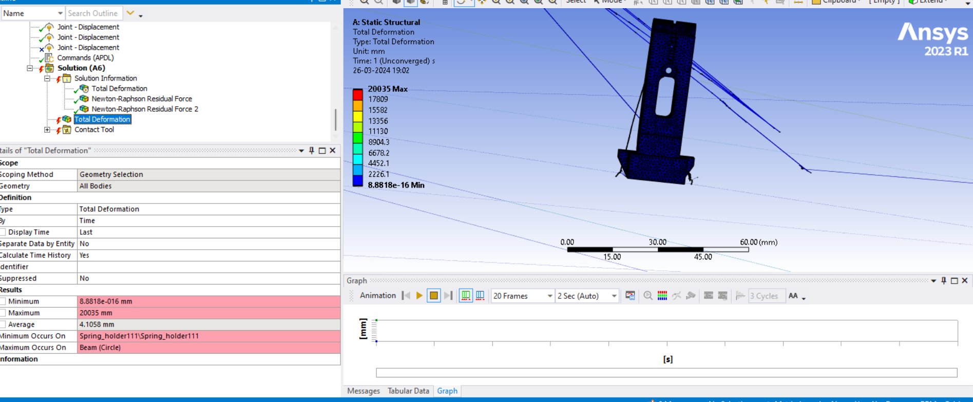
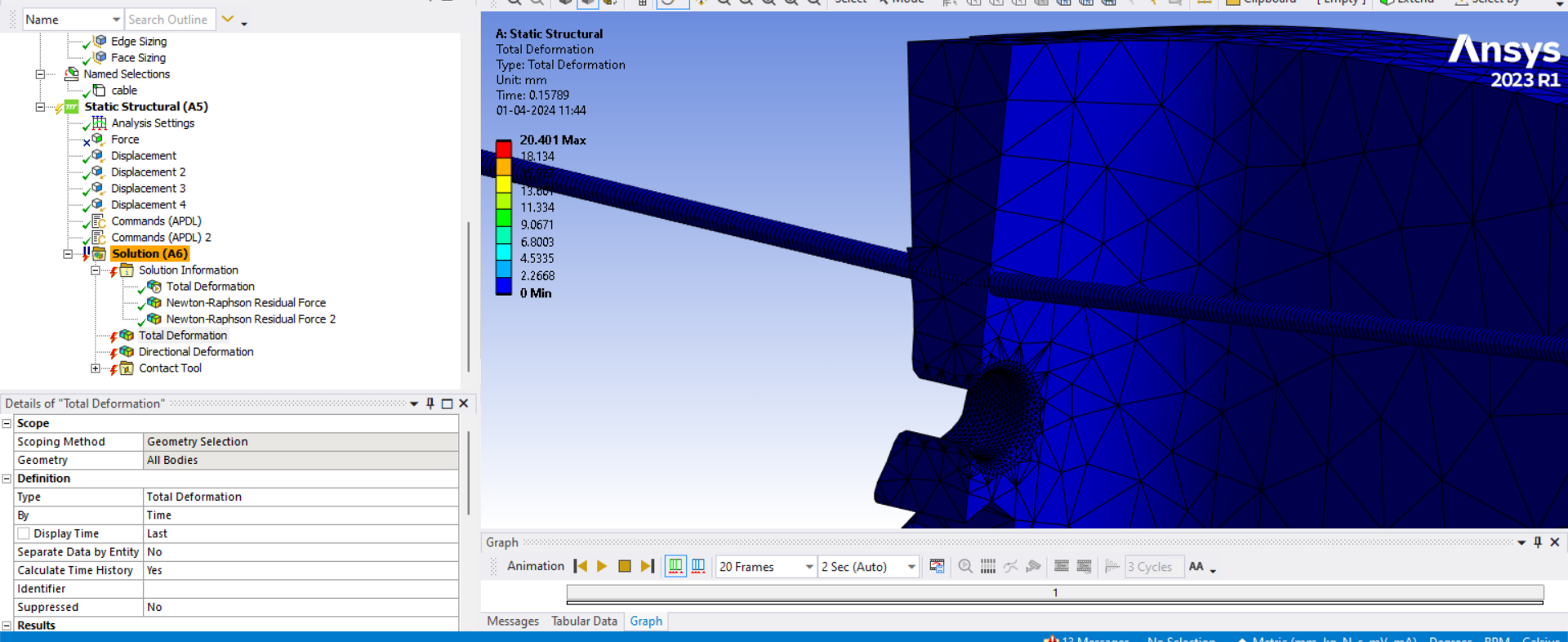
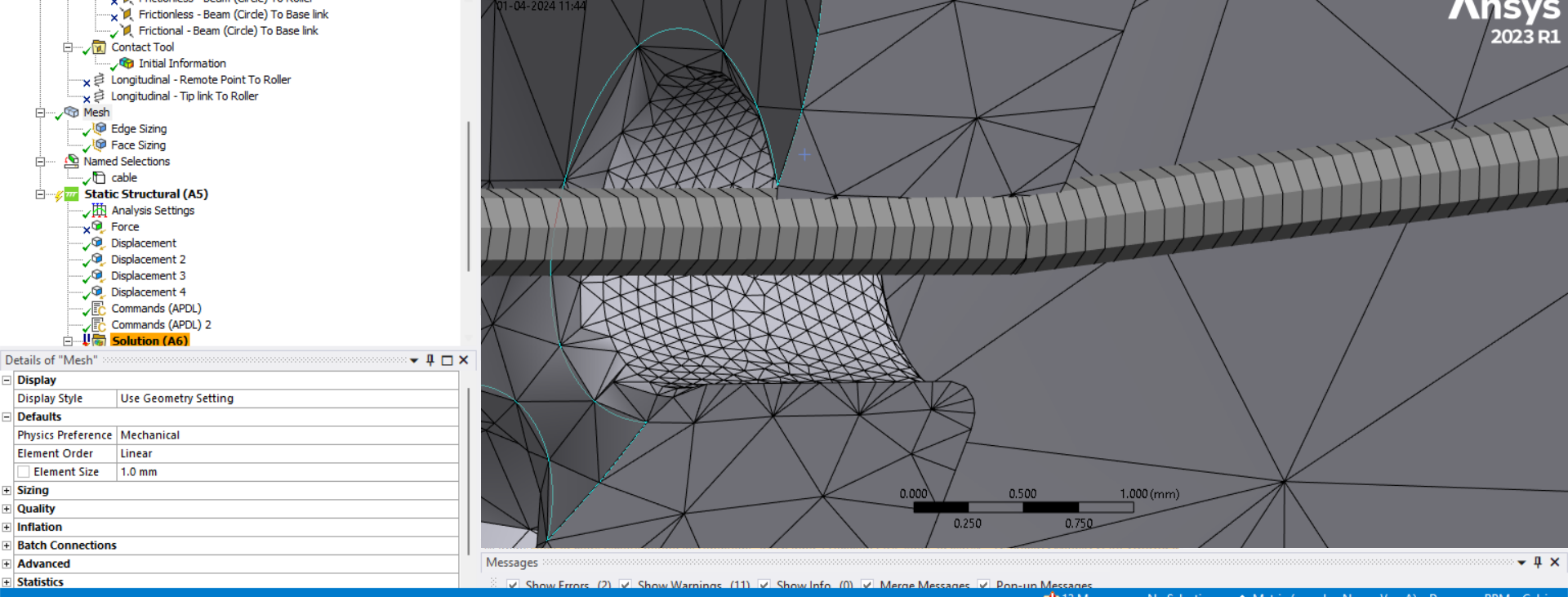
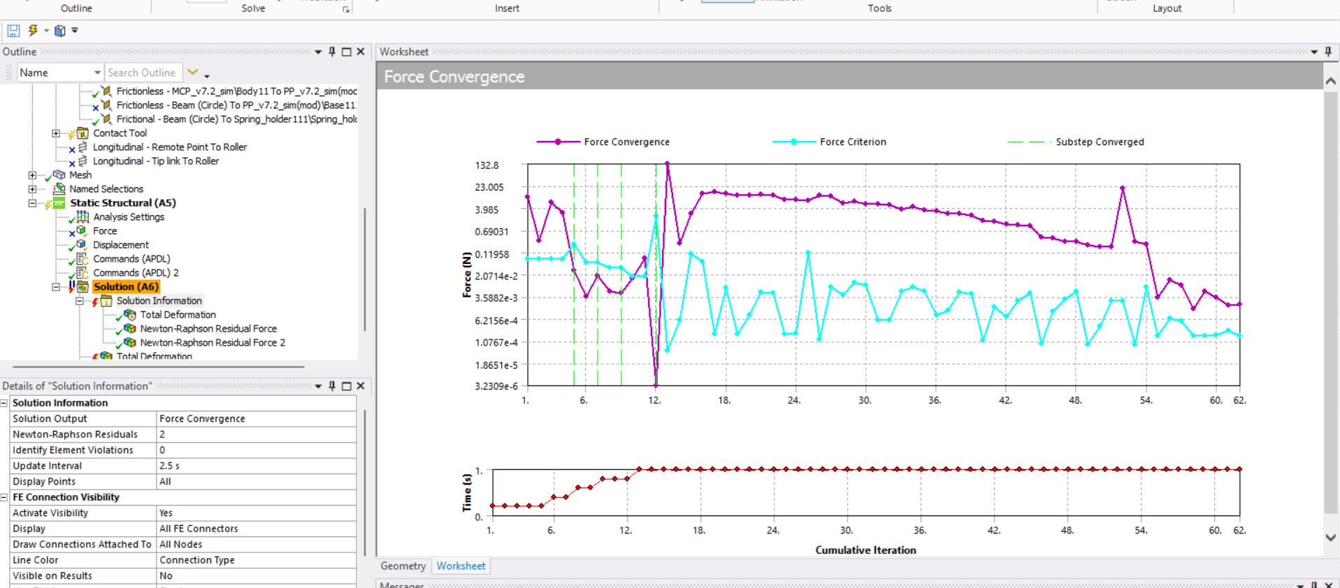
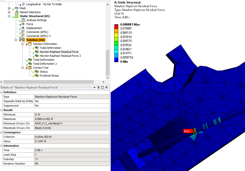
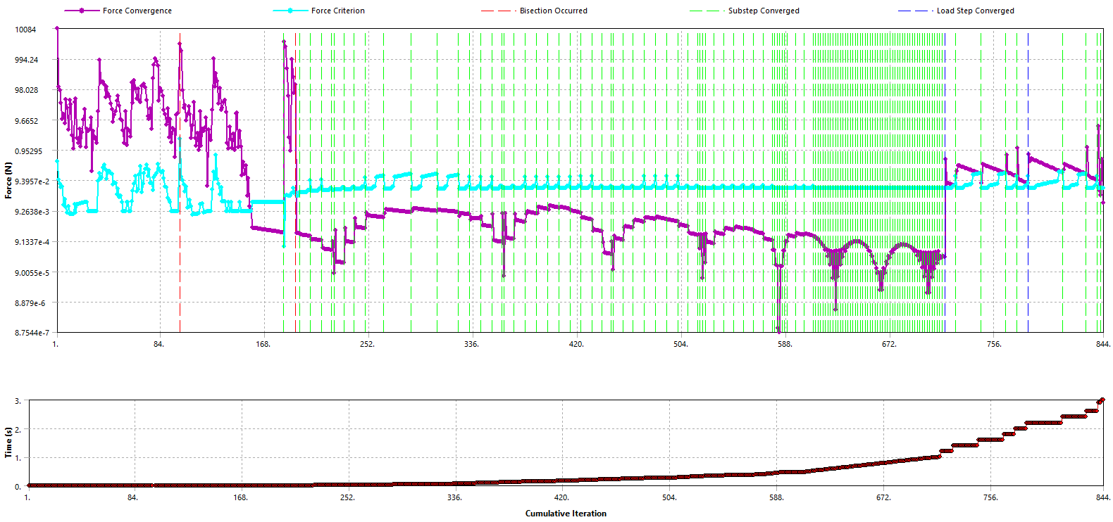
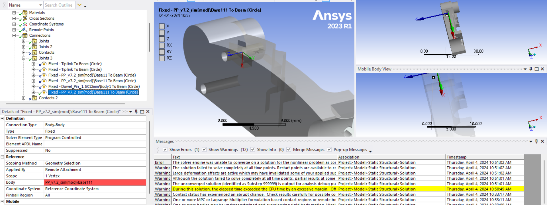
SubscriberThe reason you request Newton-Raphson Residual Force plots is to find out where the solver is having trouble converging on a force equilibrium. As you can see below, it is where the wire is bending over a sharp edge.
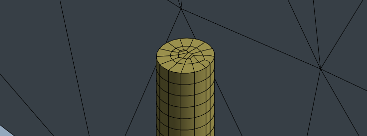
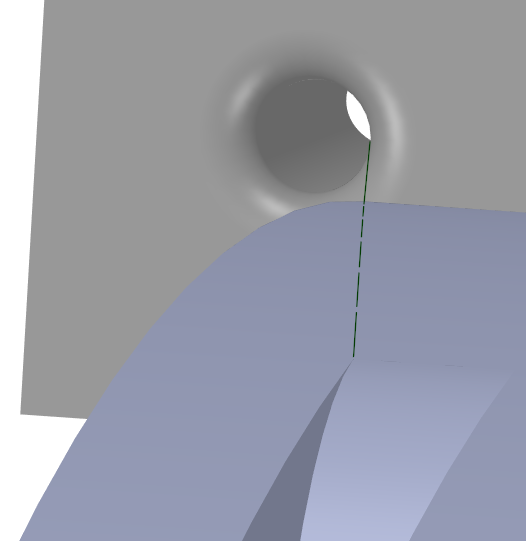
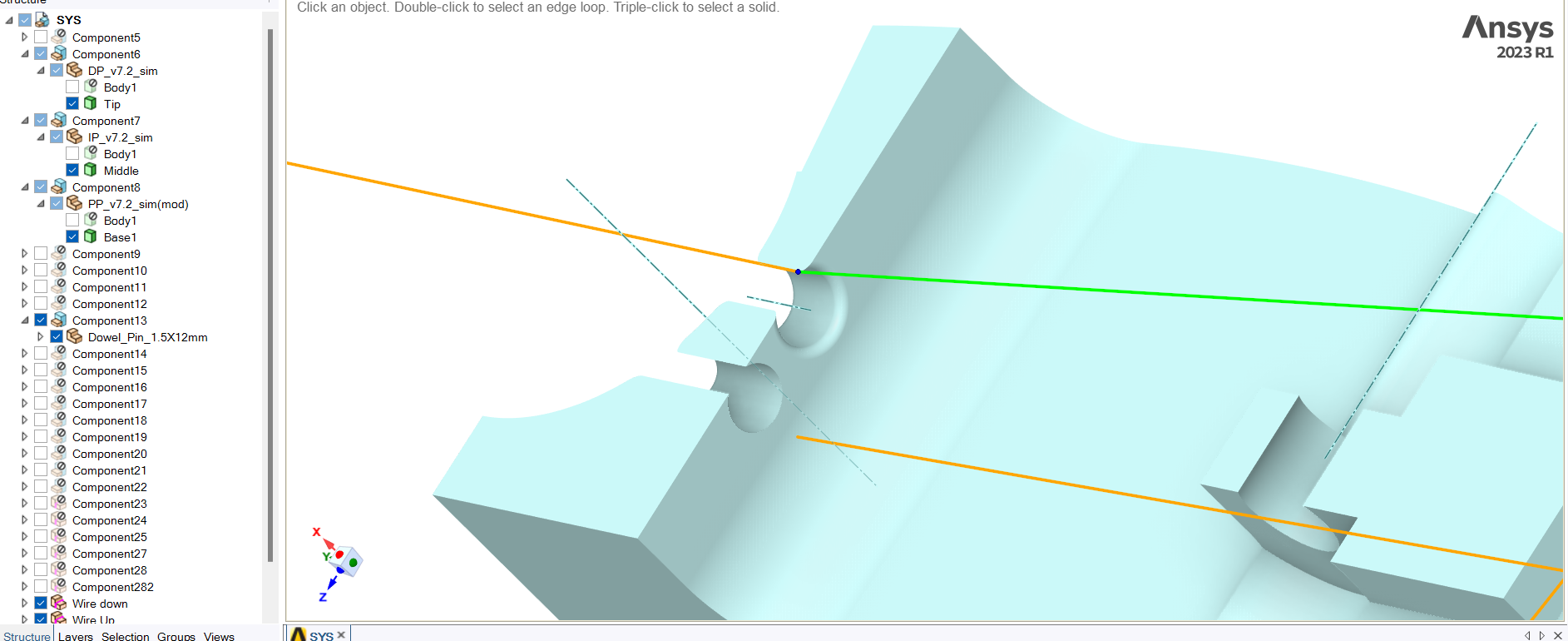
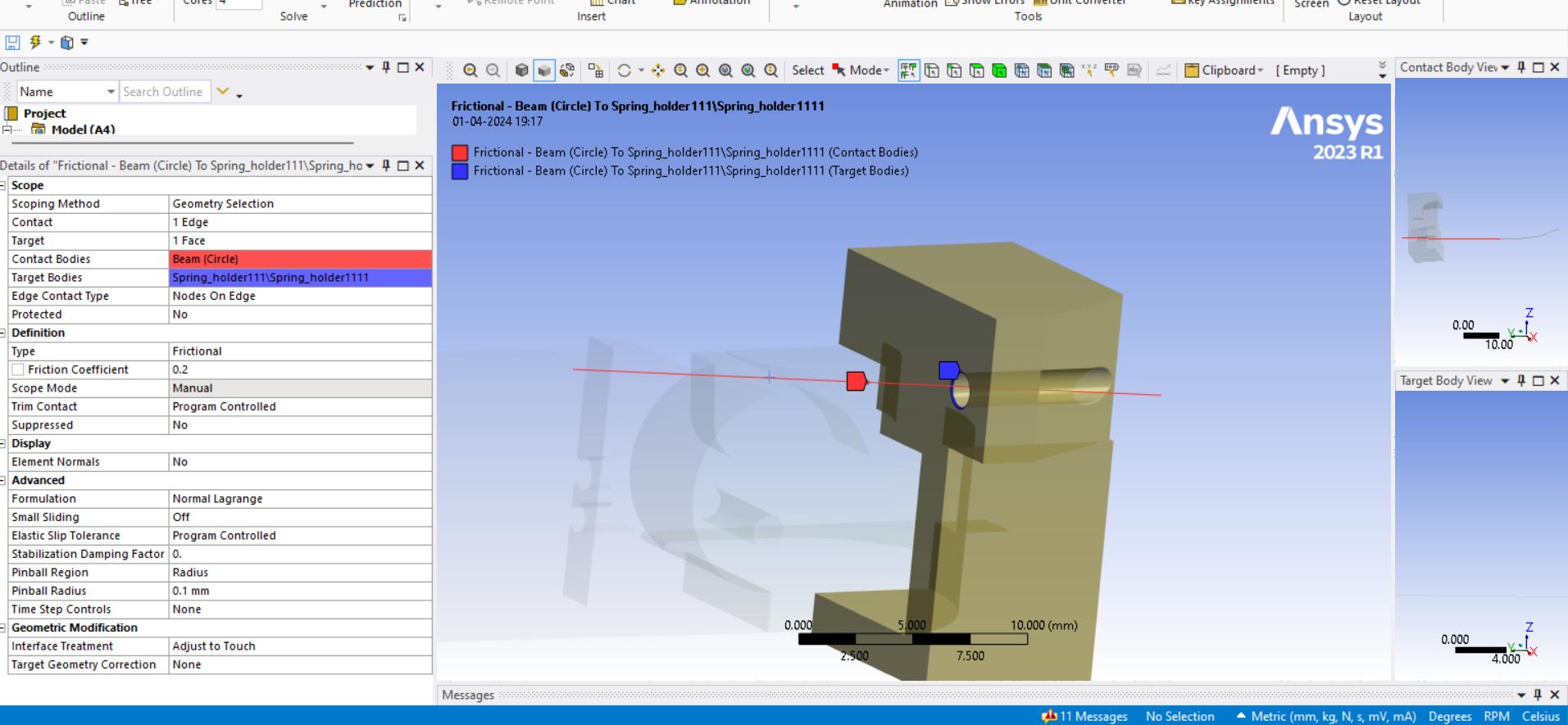
It was a bad idea to have the wire bend over a sharp edge in order to reach down to the dowel pin in the FEM. It would be a good idea to end the wire at that corner so that it never has to bend over that edge.
If you really want the wire bending over that edge, then you should put a blend radius on that edge but I would not do that. Just terminate the wire at the corner.
-
April 3, 2024 at 9:50 am
peteroznewman
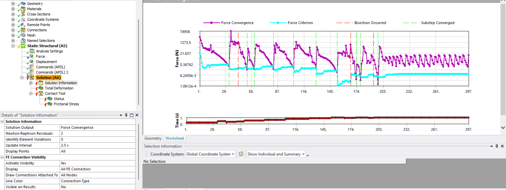
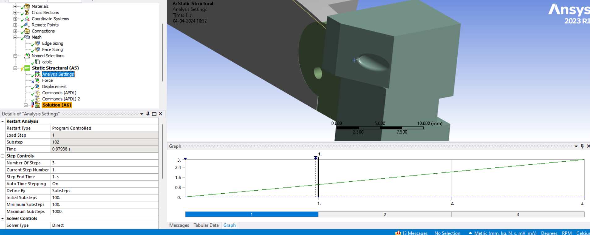
SubscriberThis is the result of removing the last segment of wire and redefining the Fixed Joint to holding the next vertex. The other change was to set the Initial and Minimum Substeps to 100 and the Maximum Substeps to 1000.
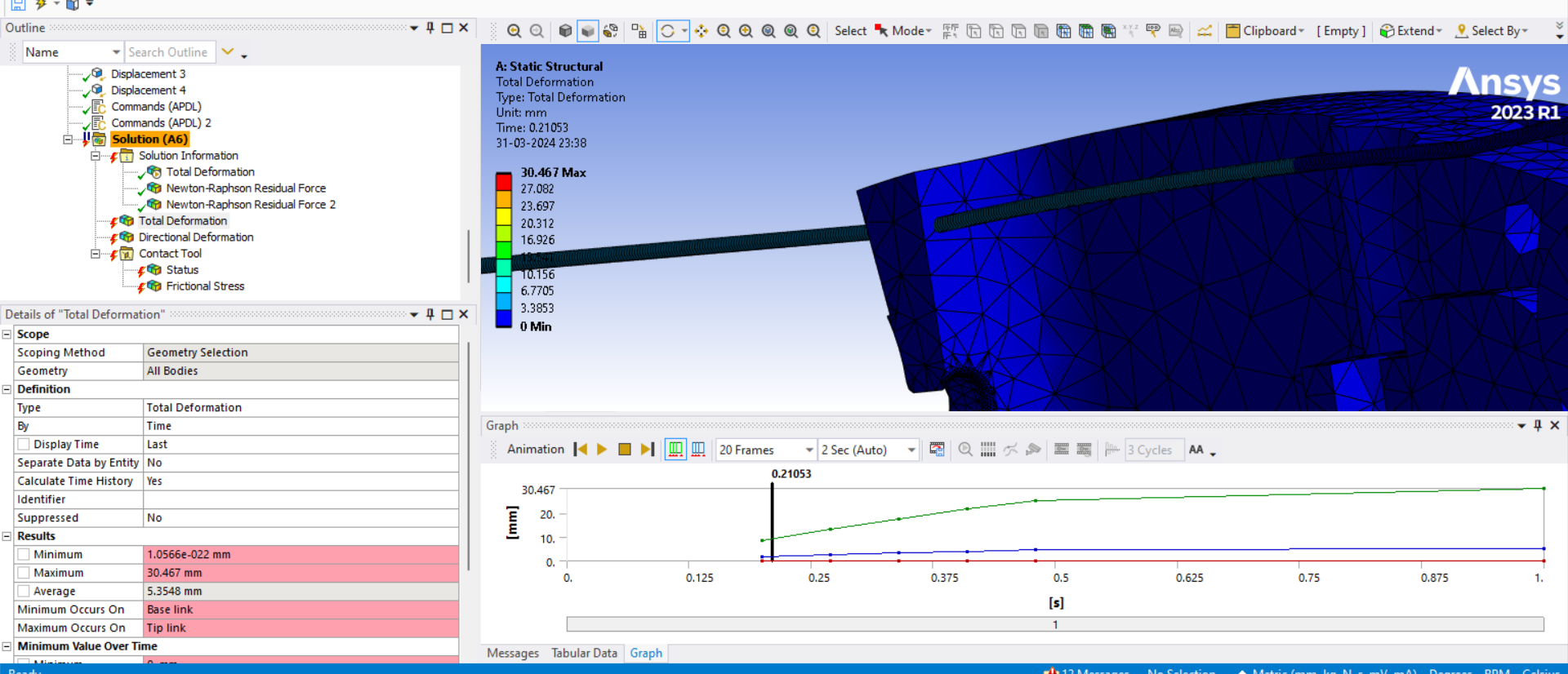
Notice that the solver can’t get started, and has bisection before the first converged substep after 5 iterations with this warning:
    EQUIL ITER   5 COMPLETED.  NEW TRIANG MATRIX.  MAX DOF INC= -0.2124

 *** WARNING ***                         CP =       7.641   TIME= 21:22:20
 Contact element 85693 (real ID 10) status changes abruptly from contact
 (with target element 86405) -> no-contact.
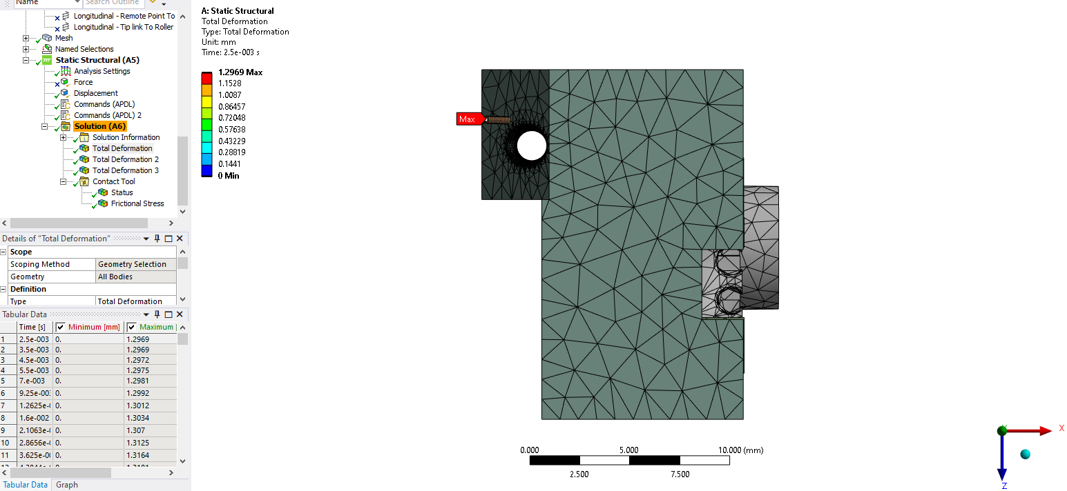
Below is the displacement of the first converged substep. Notice that the wire has left the hole at the very first substep
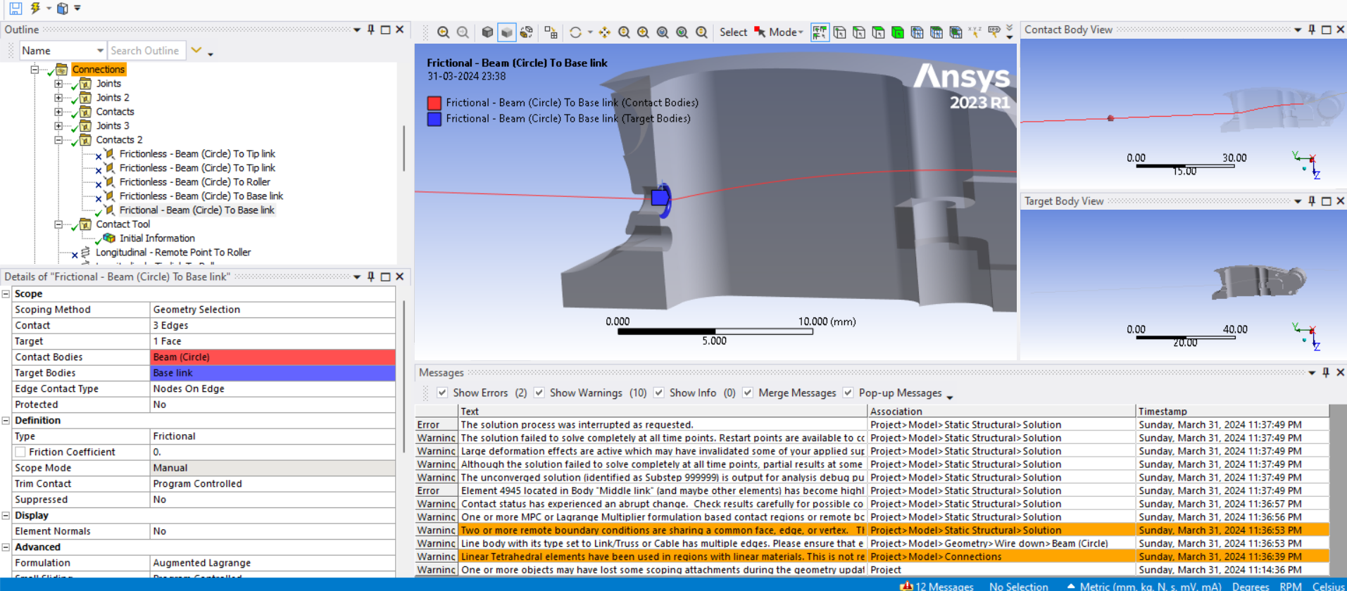
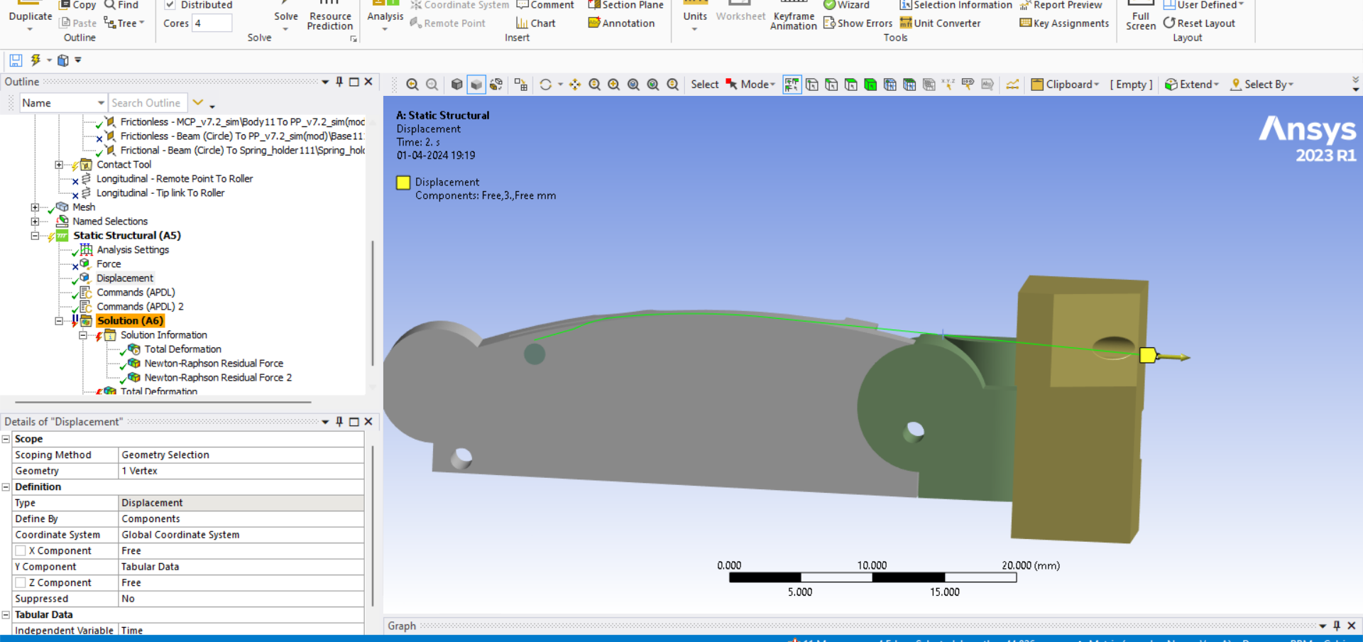
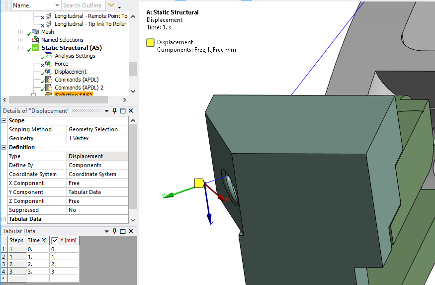
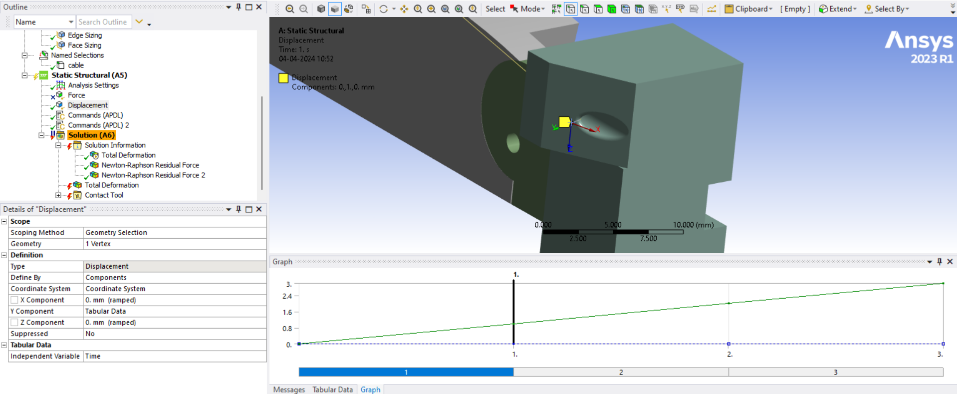
The Displacement condition shown below leaves the end of the wire Free in two directions. This is a bad idea. The wire is being pulled in a straight line along that local Y axis. Why not fix those two directions at 0, that would be a more stable configuration.
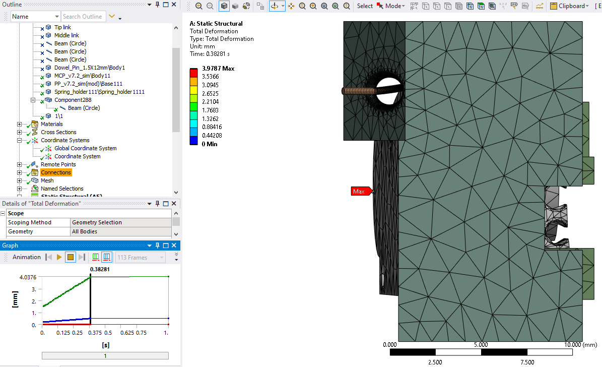
Making this suggested change results in the wire staying in the hole.
-
April 3, 2024 at 4:12 pm
-
April 3, 2024 at 6:19 pm
ROHITH
SubscriberI HAVENT GIVEN ANY CONTACT AT THE ENTRANCE AS THERE IS A LIMIT TO THE ROTATION IN THE ACTUAL CONDITION AND I THINK THE MOTION IS ENOUGH THAT YOU GOT THANKS PETER. THANK YOU FOR YOUR GUIDENCE. COULD YOU JUST SHARE ME THE ARCHIVE FILE OF IT I WANT TO SEE THE CHANGES YOU MADE TO GET THIS CONVERGENCE
-
April 3, 2024 at 8:19 pm
peteroznewman
SubscriberThe few changes I made are described above. It will be good practice for you to apply them yourself.
One problem with this model is there is no tension in the wire. There is no opposing spring on the other side that is tensioning the wire. Moving parts with practically zero tension in the wire can lead to instability. Add a resisting spring on the opposite side of the link for the wire to pull against.
-
April 3, 2024 at 8:43 pm
ROHITH
SubscriberILL DO THAT AS IM GOING TO SOLVE THE MODEL STEP BY STEP BUT PETER I HAVE TRIED MANY TIMES WITH THE CHANGES YOU SUGGESTED BUT ITS NOT WORKING FOR ME ITS EVEN FAILING AT 0.6 SEC CHANGED THE DESIGN MANY TIMES STILL NOT WORKING
-
-
April 3, 2024 at 9:07 pm
peteroznewman
SubscriberApply the following changes to the last model you archived above and you should get the same result I got.
- Delete the fixed end segment in SpaceClaim.
- Repair the Fixed Joint and attach it to the new vertex.
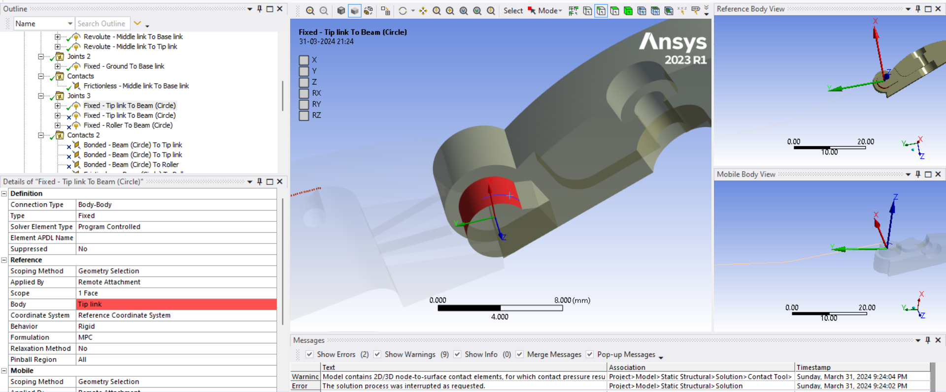
- Check that the Line body is still Truss/Link, it automatically reverts to Beam when you import the modified geometry.
- Edit the Displacement and change the two rows of Free to 0.
- Edit the Anaysis Settings and make step 1 have 100 Initial and Minimum substeps and 1000 Maximum Substeps.
-
April 4, 2024 at 5:24 am
-
- The topic ‘Analysis of Robotic Finger’ is closed to new replies.


-
5179
-
1838
-
1387
-
1249
-
1021

© 2026 Copyright ANSYS, Inc. All rights reserved.

.png)
